SW2 L4-1.9L DOHC VIN 7 (1997)

Tester (SA 9130Z) and the other method is with a digital multimeter.
Continuity/Resistance/Diode
This group of settings on a multimeter allow you to accurately test for continuity and determine the resistance of many vehicle components.
Continuity
To check for continuity in a circuit use the lowest ohm scale available. Place the leads of the multimeter on each end of the circuit or component
being tested. A reading of less than one ohm indicates acceptable continuity.
Resistance
To test for resistance values, place the leads of the multimeter on each side of the circuit or component being tested. Adjust the ohm settings on the
multimeter until an acceptable reading is displayed. The lowest scale that gives a reading without going over the range (1 or OL) gives the most
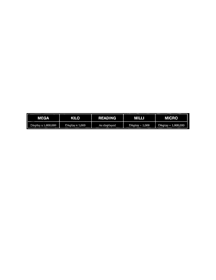
accurate reading. Compare the reading displayed on the multimeter to the specification found in the Multimeter Display Reading or bulletin.
Verify that the scale reading on the multimeter is the same as in the specification (megohms, kilo-ohms or ohms). See: Digital Multimeter
Usage/Multimeter Display Reading
NOTE: when using a multimeter on the ohmmeter or diode test scale, make sure the circuit or component is disconnected from a power source.
Applying voltage to a multimeter when you are measuring resistance can damage the multimeter.
Diode Testing
Most digital multimeters have a Diode setting. This setting is used to test a diode to verify current flows in only one direction.
A good diode will display between 0.4 and 0.8 volt on the meter when the leads are forward biasing the diode, this indicates the diode is allowing
current to flow in that direction. When the leads are reversed, the meter should read 1 or 0L, indicating the diode is blocking the flow of current in
the opposite direction. This indicates a good diode. If the diode allows current flow in both directions or prevents current flow in both directions,
the diode is damaged and should be replaced.
Multimeter Display Reading
Electrical Circuits Diagnosis
Before beginning any diagnosis, there are several important steps that should be taken:
Verify the Problem
Operate the system and list symptoms in order to:
^
Check the accuracy and completeness of the concern.
^
Learn more what might give a clue to the nature and location of the problem.
^
Analyze what parts of the system are working.
Check the Circuit Schematic
Refer to the circuit schematic for clues to the concern. Location and identification of circuit components may give some idea of where the problem
is.
The circuit schematics are designated to make it easy to identify common points in circuits. This knowledge can help narrow the problem to a
specific area. For example, if several circuits fail at the same time, check for a common voltage or ground connection. If part of a circuit fails,
check the connections between the part that works and the part that does not work.
Cause-to-Complaint Charts
Refer to the Cause-to-Complaint charts. This chart lists the types of problems that may be encountered in an electrical circuit and the possible fix.
The chart will then refer you to the correct diagnosis step. Use the electrical schematic along with the diagnosis steps to help in troubleshooting.
Graphic Overview
Graphic overview illustrations are shown for each circuit. These illustrations can be used to help locate a component and/or connector while
diagnosing.
General Description
The general description, describes how the circuit operates, when the circuit operates and how the components interact to make a complete circuit.
Connector Views
These Connector Views can be used to help show what the connector looks like and where a particular terminal in the connector is located.
Make the Repair
Repair the problem circuit as described in Diagnostic Aids.
