
SW2 L4-1.9L DOHC VIN 7 (1997)
internal conversion of these voltages to binary data by the PCM. However, the voltages should generally vary together and the difference should
be less than 0.2 volt.
^
The diagnostic service probe can be used with future test equipment to gain access to a circuit for testing or calibration.
^
The diagnostic service probe can be used to give a good ground access point. Attach a diagnostic service probe to a ground circuit and insert the
multimeter lead in the probe at a ground reference. Check the ground circuit to verify the ground path is good.
Installation
Service Probe Installation
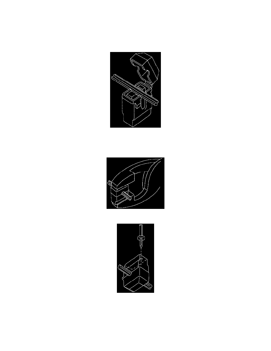
1. Place the cable into the V-slot of the terminal.
2. Press the cable into the V-slot by hand and initiate closing the cover.
Service Probe Installation
Service Probe Installation
3. Close the cover completely by pressing the cable into the diagnostic service probe terminal with pliers until the cover locks shut. A snap should be
felt or heard when the cover locks.
4. To probe the wire, insert the multimeter probe into the housing through the gel to contact the terminal. The housing has a thin wall of material to
pierce with the multimeter probe. In some locations the multimeter probe should be used to pierce the probe opening, before the probe is installed
on the wire.