SW2 L4-1.9L DOHC VIN 7 (1997)

Verify that the Repair is Complete
Operate the system and check that the repair has removed all symptoms, and also has not caused any new symptoms.
Introduction to Diagnosis of Electrical Faults
A digital multimeter is required to quickly and accurately diagnose most electrical faults. Due to the complexity of the circuitry and the use of electronic
components, a multimeter is required to safely test the electrical circuits on a Saturn vehicle. A test light should not be used to troubleshoot electrical
circuits on a Saturn vehicle.
A test light is a low-resistance load on an electrical circuit. On most test lights used today, this low-resistance is 50 ohms. Since electronics are designed
to be used with high-resistance circuits, using a low-resistance test light can cause damage to an electronic module. Another problem that occurs when
using a test light is accuracy. During some testing procedures, you will be asked to test for a certain voltage. For example, from 8 - 16 volts. With a test
light it is impossible to determine the difference between 5 volts and 8.0 volts. A digital voltmeter will display the exact voltage on a circuit.
Another problem with test lights are the sharp probe tip that is often used to probe wires. Probing a wire with a test light, or any other sharp pointed
instrument, can break strands of the wires and cause future circuit failures. Also, a break in the insulation allows the wire core to act as a wick pulling in
moisture, not only damaging the wire, but allowing it to enter connectors and components. This moisture can include salt, antifreeze and other fluids as
well as water. Some of these contaminants cause corrosion in the wire or connector. Corrosion increases a circuits resistance, and in electronic circuits,
even a small increase in resistance can give a false reading from a sensor to an electronic module.
NOTICE: Never probe secondary ignition wires, for any reason. Small pin holes in secondary ignition wires allow high voltage from the coil to arc from
the wire to a metal part, external to the secondary ignition circuit. This arcing can cause the engine to miss-fire, causing a driveability complaint.
Push-to-Seat Connectors
IMPORTANT: Cut leads with terminals are available from Saturn Service Parts for terminal replacement.
TERMINAL REMOVAL
Push-To-Seat Connectors
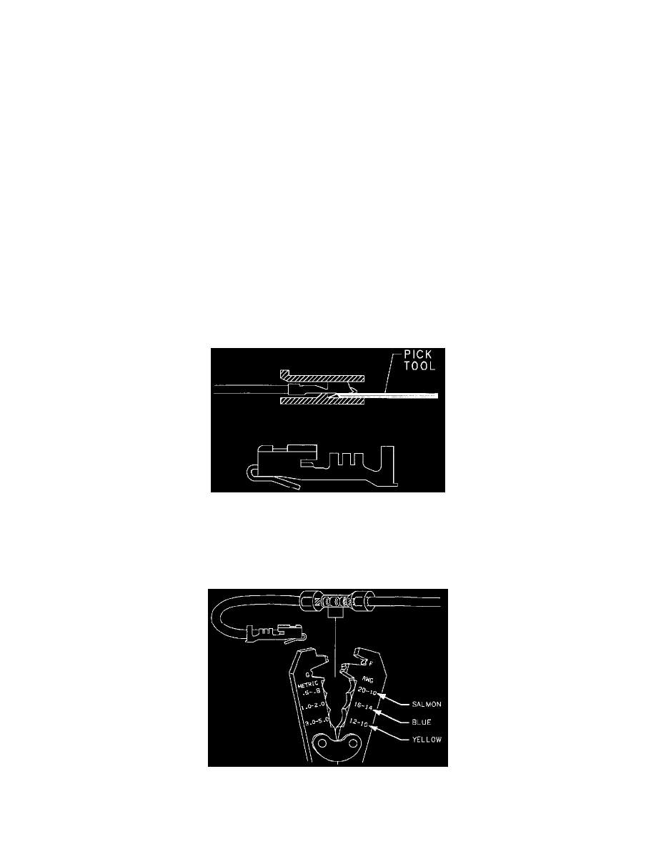
1. Remove any Terminal Position Assurance (TPA) locks.
2. Insert the terminal lock release tool into the front of the connector cavity. Pull the wires and terminal out of the back of the connector.
CUT LEAD INSTALLATION
Push-To-Seat Connectors
1. Put connector seal (if equipped) on wire and strip approximately 9.5 mm (3/8 in.) of insulation off the wire.
