
VUE L4-2.2L VIN D (2002)
Splice Packs
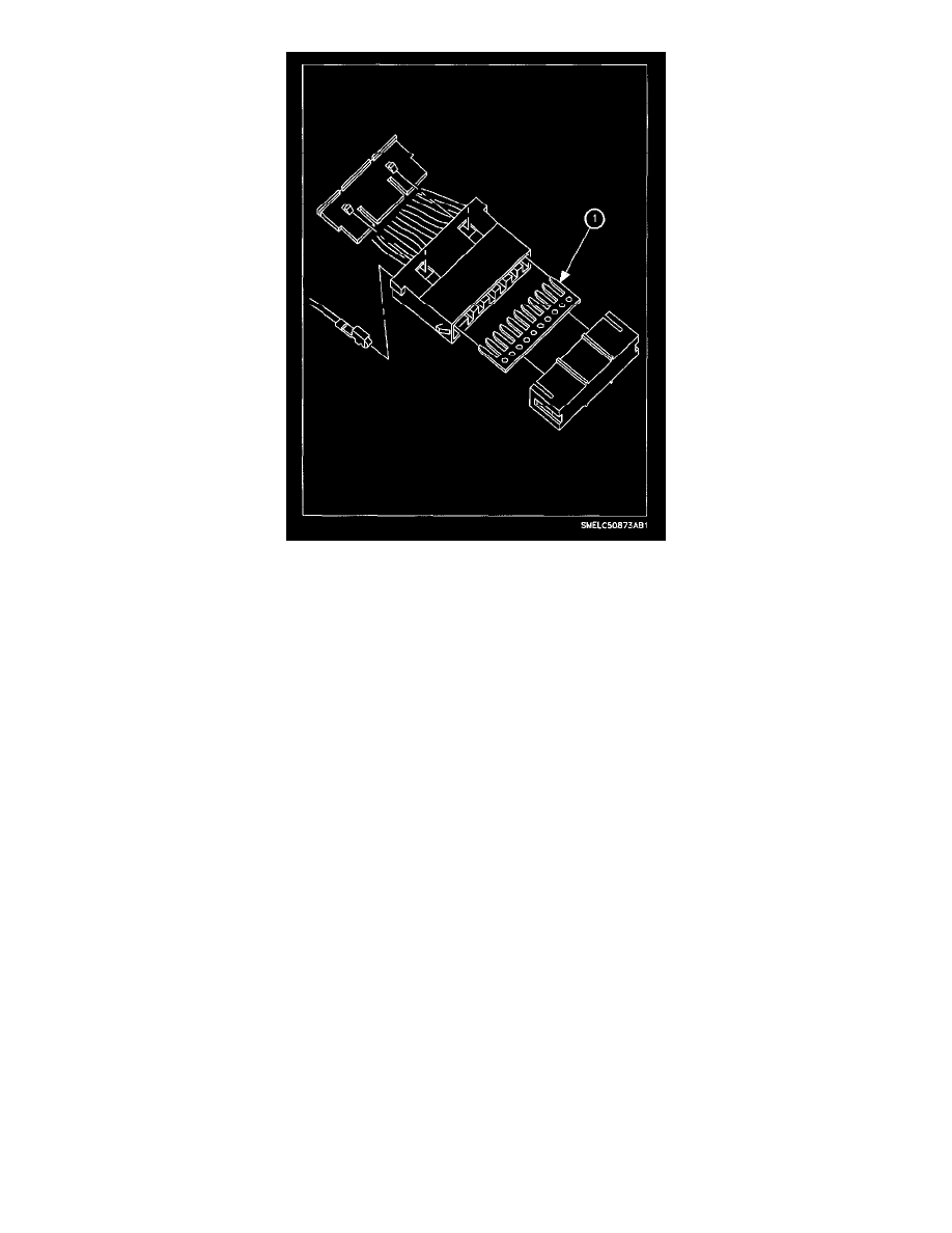
Splice packs are used to replace conventional soldering and clipped splices. The splice pack consists of a buss bar (1) with male blades that plug into a
standard female crimp on terminal. A plastic cover is placed over the buss bar to insulate it from surrounding wires and the environment. This feature
improves the reliability of splices.
Some of the grounding splice packs have an integral ring terminal as part of the buss bar. This way the splice pack can be directly connected to the
vehicle body instead of using a wire to go from the splice pack to a ring terminal.
Vehicle Electrical Diagnosis
NOTE: When troubleshooting an electrical system, make sure there are no electrical loads ON, except for the circuits or system being tested. This will
help prevent false readings and the chance of a dead battery. After the car has been serviced, always visually inspect the battery to be sure the Green Eye
is visible in the battery hydrometer.
Before Trouble Shooting
1. Visually inspect wires and connectors.
2. Verify that terminal pins are clean and that there are no loose pins or terminals.
3. Verify that the Weather-Pack connectors are in good condition and sealed properly.
4. Check the minifuse, maxifuse or circuit breaker used to protect the circuit or system being tested.
5. Check the battery for damage, state of charge, and for clean and tight connections.
6. Check the accessory drive belt.
Five-Step Trouble Shooting
1. Verify the complaint.
^
Perform System Performance Test, if section has one outlined at the beginning of section.
^
Learn more about the nature and location of the problem. Use the general description to learn how the circuit operates, when the circuit should
operate, and how the components interact to make the circuit complete.
^
Analyze what parts of the system are working.
^
Do not fix only part of the problem.
^
Do not begin disassembly or testing until you have narrowed down the possible causes.
2. Analyze the electrical schematic and consult the flowcharts for the system being tested.
^
Look at the electrical schematic for the problem circuit. Determine how the circuit is supposed to work and look for minifuses, maxifuses,
circuit breakers, wires, and grounds that are shared with other systems or components. See if a shared wire is at fault by checking other
components fed by the wire. If several circuits fail at the same time, check for a common voltage or ground connection. If part of a circuit fails,
check the connections between the part that works and the part that does not work.
^
Follow the flowcharts to find the possible cause(s) of the problem.