
VUE AWD L4-2.2L VIN D (2005)
Crankshaft Position Sensor: Description and Operation
CRANKSHAFT POSITION (CKP) SENSOR
The crankshaft position (CKP) sensor is a permanent magnet generator, known as a variable reluctance sensor. The CKP sensor produces an AC voltage
of different amplitude and frequency. The frequency depends on the velocity of the crankshaft. The AC voltage output depends on the crankshaft
position and the battery voltage. The CKP sensor works in conjunction with a 7X reluctor wheel attached to the crankshaft. The CKP sensor produces
seven pulses for each revolution of the crankshaft. The pulse from the 10-degree notch is known as the sync pulse. The sync pulse is used to synchronize
the coil firing sequence with the crankshaft position. The CKP sensor is used for ignition timing, the fuel injector timing, misfire diagnostics and
tachometer display. The CKP sensor is connected tot he ECM by a signal circuit and a low reference circuit.
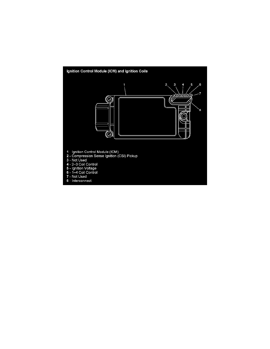
Ignition Control Module (ICM) And Ignition Coils
The powertrain control module (PCM) supplies a signal on each of the ignition control (IC) timing control circuits to the ignition control module (ICM).
The ICM fires the correct ignition coil at the correct time based on the signals. The ICM detects if cylinder 1 or cylinder 3 is on the compression stroke
by sensing the secondary voltage and polarity of each side of the ignition coil. The ICM detects this voltage with sensing circuitry integrated into each
ignition coil. The higher voltage is on the compressing cylinder. This is called compression sense ignition. The ICM provides a synthesized cam signal to
the PCM based on these inputs. The PCM uses the cam signal to synchronize fuel injection. This system consists of the following circuits:
-
An ignition voltage circuit
-
A ground circuit
-
A camshaft position (CMP) sensor signal circuit
-
An IC timing control circuit for cylinders #1 and #4
-
An IC timing control B circuit for cylinders #2 and #3