
VUE AWD L4-2.2L VIN D (2005)
Main Relay (Computer/Fuel System): Testing and Inspection
MAIN RELAY DIAGNOSIS
CIRCUIT DESCRIPTION
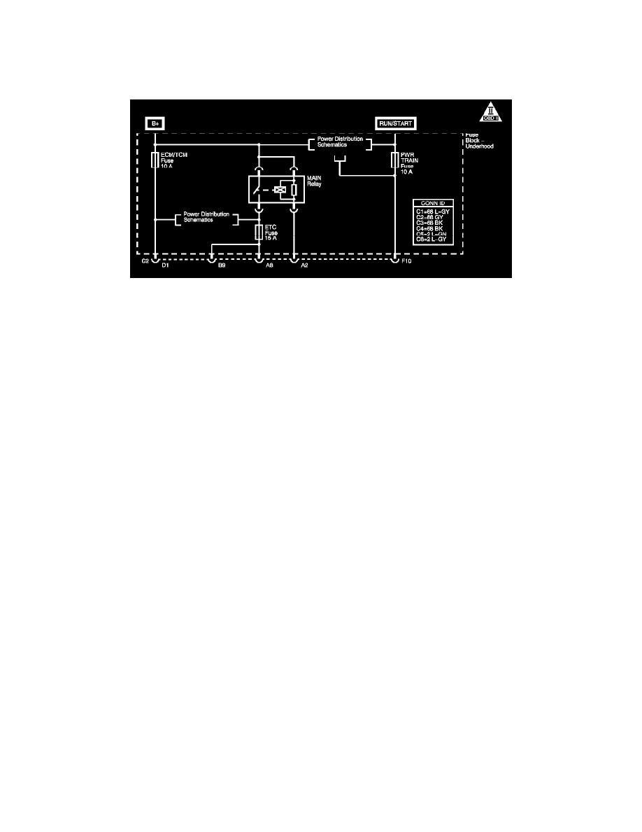
The main relay is a normally open relay. The relay armature is held in the open position by spring tension. Battery positive voltage is supplied directly
to the relay coil and the armature contact at all times. The engine control module (ECM) supplies the ground path to the relay coil control circuit, via
an internal integrated circuit called an output driver module (ODM). When the ECM commands the relay ON, the relay coil creates an electromagnetic
field. This electromagnetic field overcomes the spring tension and pulls the armature contact into the stationary contact of the relay load circuit. The
closing of the relay contacts allows current to flow from the battery to the following fuses:
-
ETC FUSE
-
EMISSION FUSE
When the ignition switch is turned to the OFF position, power is interrupted to the output driver module in the ECM, and the relay electromagnetic
field collapses. This allows the spring tension to separate the relay armature contact from the relay load circuit contact, which interrupts current flow
to the fuses.
If the main relay fails to close the engine will crank and run. The class 2 communications will be available with the use of a scan tool.
The main relay system diagnosis table assumes that the vehicle battery is fully charged. Refer to Battery Inspection/Test (Side Terminal Battery)
Battery Inspection/Test (Top Post Terminal Battery) in Starting and Charging. See: Starting and Charging/Testing and Inspection/Component Tests
and General Diagnostics/Battery Inspection/Test - Side Terminal Battery See: Starting and Charging/Testing and Inspection/Component Tests and
General Diagnostics/Battery Inspection/Test - Top Post Terminal Battery
TEST