
VUE AWD V6-3.5L (2007)
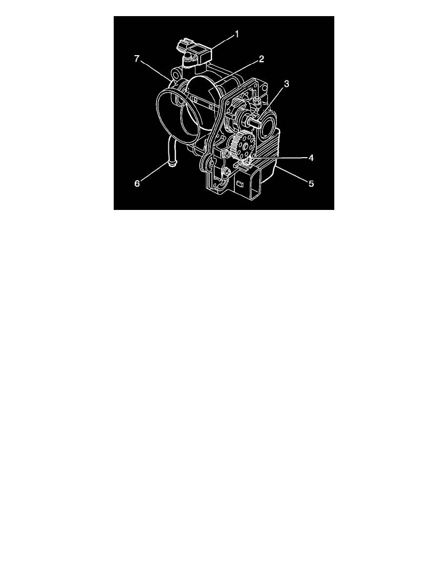
1
- Manifold Absolute Pressure (MAP) Sensor
2
- Throttle Valve, Plate
3
- Throttle Shaft
4
- Throttle Control Motor Drive Gear
5
- Throttle Actuator Control (TAC) Module Cover
6
- Engine Coolant Pipe
7
- Throttle Body Housing
The throttle body functions similar to a conventional throttle body with the following exceptions:
*
An electric motor opens and closes the throttle valve.
*
The TAC module is an integral part of the throttle body assembly.
*
The throttle valve is spring loaded and the default position is slightly open.
*
There are 2 individual throttle position (TP) sensors integral to the TAC module cover.
The TP sensors are used to determine the throttle plate angle. The TP sensors provide the TAC module with a signal voltage proportional to throttle plate
movement. Both TP sensor signal voltages are low at closed throttle and increase as the throttle opens. TP sensor 1 determines the actual throttle valve
position. TP sensor 2 provides a backup value for TP sensor 1.
Throttle Actuator Control (TAC) Module
The throttle actuator control (TAC) module is the control center for the TAC system. The TAC module uses Read Only Memory (ROM) and Random
Access Memory (RAM) along with an analog/digital (A/D) converter to control engine speed. The TAC module is self-diagnosing and communicates to
the powertrain control module (PCM) with a dedicated serial data line. The TAC module receives accelerator pedal position (APP) sensor information
from the PCM and provides diagnostic information to the PCM.
The APP sensor 1 enables the PCM to provide a target value to the TAC module in response to accelerator pedal movement. The TAC module achieves
the correct throttle position by commanding the throttle control motor to position the throttle valve at the target value. The TAC module then compares
the throttle position (TP) sensor 1 value to the target value. If necessary, the throttle control motor is moved slightly to obtain the exact desired position.
The TAC module is not serviced separately and must be replaced with the throttle body assembly.
Powertrain Control Module
The powertrain control module (PCM) determines the drivers intent and then calculates the appropriate throttle response. This information is sent to the
throttle actuator control (TAC) module through a dedicated serial data line.
Modes of Operation
Normal Mode
During the operation of the throttle actuator control (TAC) system, several modes or functions are considered normal. The following modes may be