
VUE AWD V6-3.5L (2007)
Engine Control Module: Description and Operation
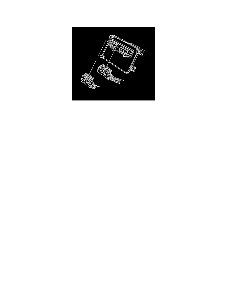
Powertrain Control Module Description
The powertrain control module (PCM) is a precision 32-bit microprocessor and is an essential part of the electronic control system. The PCM is located
underhood on the right side of the engine compartment. The PCM uses a KW2000 communication protocol. Communication with the PCM is through
the data link connector located on the left side of the passenger compartment below the IP.
The PCM performs the OBD II diagnostic tests of the emission related systems. The PCM supplies a buffered voltage, called reference voltage, to the
various information sensors and switches. The PCM controls most components with an electronic switch that completes a ground circuit when turned
ON. The electronic switch is commonly referred to as an output driver. The PCM is also responsible for a self-diagnosis function and a fail-safe function.
Self-Diagnosis Function
The powertrain control module (PCM) diagnoses any troubles which may occur in the engine control system when the ignition switch is in the ON
position with the engine running. The PCM indicates a malfunction by illuminating the malfunction indicator lamp (MIL) when a fault occurs in any of
the following systems:
*
The heated oxygen sensor 1 (HO2S 1)
*
The heated oxygen sensor 2 (HO2S 2)
*
The engine coolant temperature (ECT) sensor
*
The accelerator pedal position (APP) sensors
*
The intake air temperature (IAT) sensors
*
The camshaft position (CMP) sensor
*
The crankshaft position (CKP) sensors
*
The knock sensor (KS) system
*
The evaporative emission (EVAP) control system
*
The throttle actuator control (TAC) system
*
The rocker arm oil control system
*
The vehicle speed sensor (VSS)
*
The misfire detection
*
The fuel-trim
*
The catalyst monitor
*
The central processing unit (CPU) of the PCM
When the PCM detects a malfunction in one of the above areas, the PCM will illuminate or flash the MIL in order to notify the driver of the occurrence
of a fault.
Malfunction Indicator Lamp (MIL) Operation
The malfunction indicator lamp (MIL) is located in the instrument panel cluster. The MIL will display as either SERVICE ENGINE SOON or one of the
following symbols when commanded ON: