
VUE AWD V6-3.5L VIN 4 (2004)
^
If the harness has a black plastic conduit, pull out the desired wire.
2.
Cut the wire.
^
Cut no more than 25 mm (1 in) off the harness.
^
Ensure that each splice is at least 40 mm (1.5 in) away from other splices, harness branches, and connectors. This helps prevent moisture from
bridging adjacent splices and causing damage.
^
Trim new cut lead wire, P/N 22692904, to same length as damaged wire removed from connector.
3.
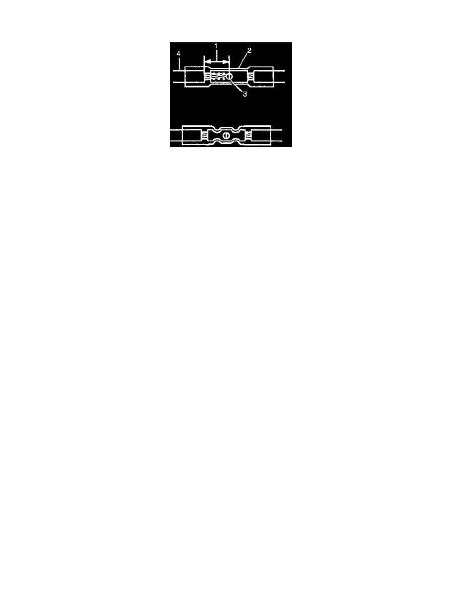
Strip the insulation. Strip approximately 7.5 mm (5/16 in) of insulation from each wire to be spliced (1).
4.
Place the provided splice sleeve in the 12085115 crimp tool nest, or equivalent, so that the crimp falls at point 1 on the splice.
5.
Close the handles of 12085115 crimp tool, or equivalent, slightly to hold the splice sleeve firmly in the proper crimp tool nest.
6.
Insert the wires into the splice sleeve until the wire hits the barrel stop. The splice sleeve has a stop in the middle of the barrel to prevent the wire
from passing through the splice (3).
7.
Close the handles of the 12085115 crimp tool, or equivalent, until the crimper handles open when released. The crimper handles will not open
until the proper amount of pressure is applied to the splice sleeve. (Repeat for other half of splice sleeve.)
Caution:
Do not use match or open flame to apply heat to seal.
8.
Shrink the insulation around the splice. Seal splice sleeve by applying heat using Ultra Torch(R) J 38125-5A, or equivalent. Heat splice sleeve to
175°C (347°F) until glue flows around edges of splice sleeve.
Important:
Verify terminal is completely seated in connector prior to putting connector back together.
9.
Reinstall new cut lead(s) into correct connector cavity.
10.
Rebuild electrical connector with reverse procedures of Steps 3 through 6. Make sure TPA retainer is seated prior to installing connector to the
PCM.
11.
If electrical tape was removed to perform wire harness inspection or repair, tape wires and harness to original condition.
12.
Verify repair by driving vehicle to ensure condition has been corrected.