
VUE FWD L4-2.4L (2008)
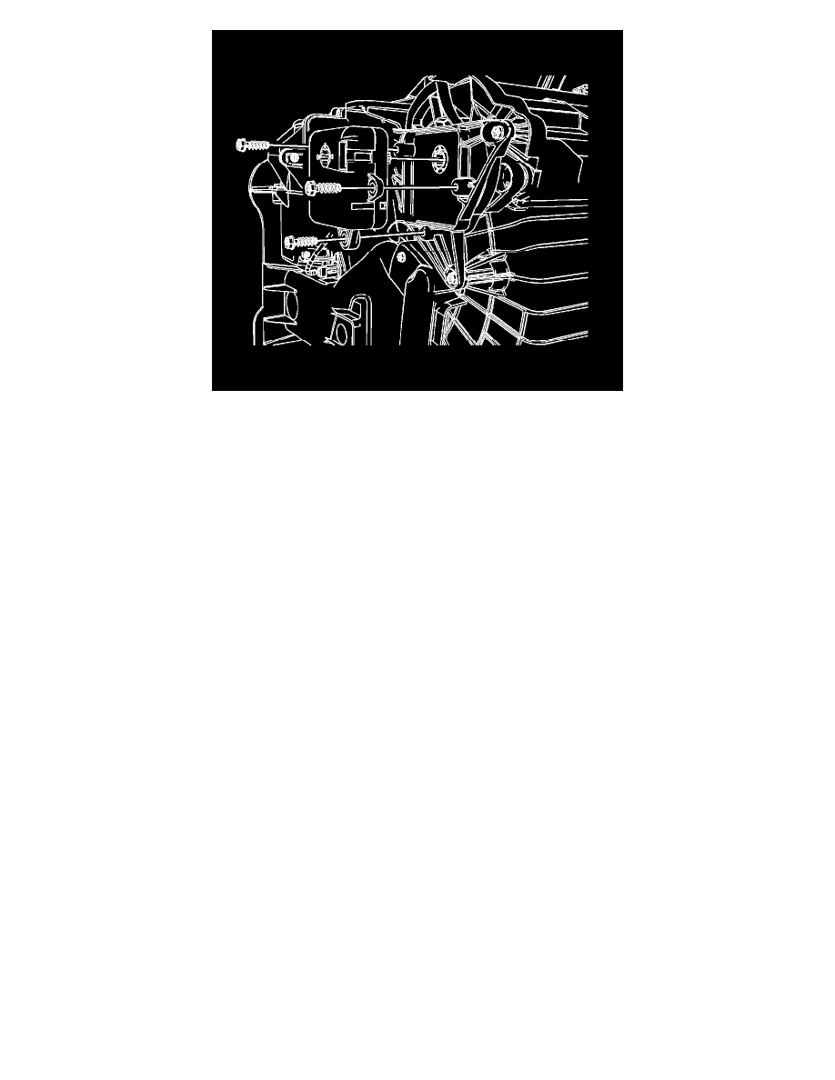
5. Install the mode actuator to the evaporator case assembly.
6. Install the mode actuator screws to the evaporator case assembly.
Tighten the screws to 1.5 N.m (13 lb in).
7. Connect the electrical connector to the mode actuator.
8. Install the communication interface module, if equipped. Refer to Communication Interface Module Replacement (See: Accessories and Optional
Equipment/Cellular Phone/Communications Control Module/Service and Repair/Communication Interface Module Replacement) .
9. Install the driver knee bolster. Refer to Driver Knee Bolster Replacement (See: Body and Frame/Interior Moulding / Trim/Dashboard / Instrument
Panel/Service and Repair) .
Important: Any time a mode actuator or the HVAC control module is replaced, the HVAC control module must be calibrated to ensure
proper air distribution.
10. Calibrate the actuators. Refer to Actuator Recalibration (See: Testing and Inspection/Programming and Relearning) .
11. Cycle the ignition and verify proper operation.
Air Temperature Actuator Replacement
Air Temperature Actuator Replacement
Removal Procedure