
VUE FWD L4-2.4L (2008)
3. Connect the electrical connector to the mode actuator.
4. Install the communication interface module, if equipped. Refer to Communication Interface Module Replacement (See: Accessories and Optional
Equipment/Cellular Phone/Communications Control Module/Service and Repair/Communication Interface Module Replacement) .
5. Install the driver knee bolster. Refer to Driver Knee Bolster Replacement (See: Body and Frame/Interior Moulding / Trim/Dashboard / Instrument
Panel/Service and Repair) .
Important: Any time a mode actuator or the HVAC control module is replaced, the HVAC control module must be calibrated to ensure
proper air distribution.
6. Calibrate the actuators. Refer to Actuator Recalibration (See: Testing and Inspection/Programming and Relearning) .
7. Cycle the ignition and verify proper operation.
Mode Control Cam Replacement
Mode Control Cam Replacement
Removal Procedure
1. Remove the driver knee bolster. Refer to Driver Knee Bolster Replacement (See: Body and Frame/Interior Moulding / Trim/Dashboard /
Instrument Panel/Service and Repair) .
2. Remove the communication interface module, if equipped. Refer to Communication Interface Module Replacement (See: Accessories and
Optional Equipment/Cellular Phone/Communications Control Module/Service and Repair/Communication Interface Module Replacement) .
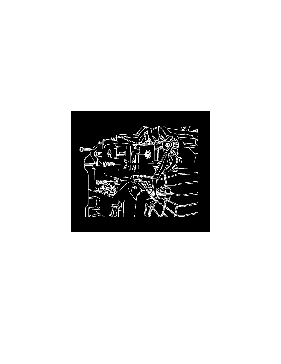
3. Disconnect the electrical connector from the mode actuator.
4. Remove the mode actuator screws from the evaporator case assembly.
5. Remove the mode actuator from the evaporator case assembly.