
VUE FWD V6-36L Hybrid (2009) Powertrain Management | Component Information
‹› If the test lamp does not illuminate, test the voltage supply circuit for a short to ground or an open/high resistance.
3. If all circuits test normal, refer to the scan tool/CANdi module user guide.
Repair Instructions
Perform the Diagnostic Repair Verification (See: Testing and Inspection/Diagnostic Trouble Code Tests and Associated Procedures/Verification Tests
and Procedures) after completing the repair.
Scan Tool Does Not Communicate with Powertrain High Speed GMLAN Device
Scan Tool Does Not Communicate with Powertrain High Speed GMLAN Device
Diagnostic Instructions
*
Perform the Diagnostic System Check - Vehicle (See: Testing and Inspection/Initial Inspection and Diagnostic Overview/Diagnostic System
Check - Vehicle) prior to using this diagnostic procedure.
*
Review Strategy Based Diagnosis (See: Testing and Inspection/Initial Inspection and Diagnostic Overview/Strategy Based Diagnosis) for an
overview of the diagnostic approach.
*
Diagnostic Procedure Instructions (See: Testing and Inspection/Initial Inspection and Diagnostic Overview/Diagnostic Procedure Instructions
)provides an overview of each diagnostic category.
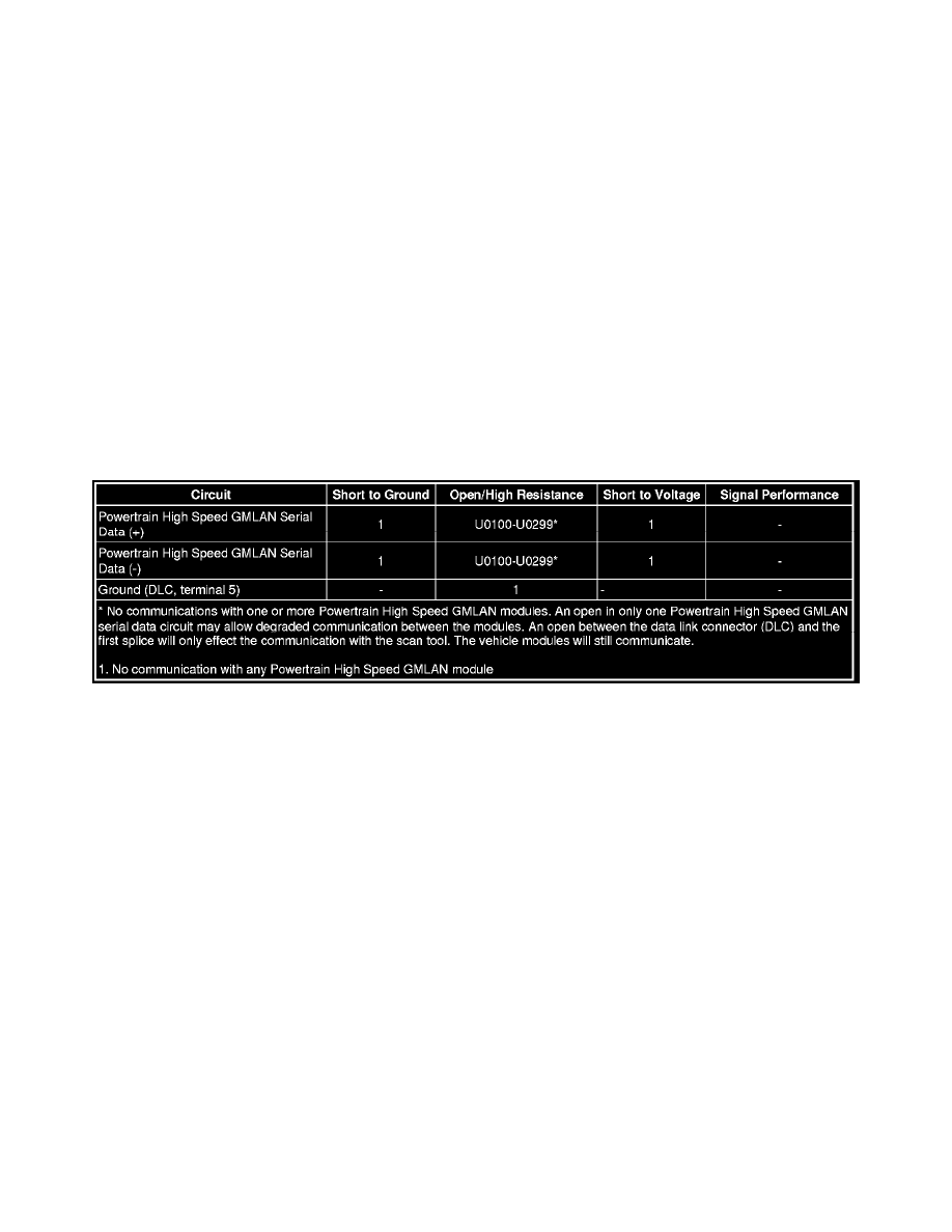
Diagnostic Fault Information
Circuit/System Description
The serial data is transmitted on two twisted wires that allow speeds up to 500 Kb/s. The twisted pair is terminated with two 120 ohms resistors, one is
internal to the engine control module (ECM) and the other can be a separate resistor in a connector assembly or in another control module. The resistors
are used as the load for the Powertrain High Speed GMLAN buss during normal vehicle operation. The Powertrain High Speed GMLAN is a differential
bus. The Powertrain High Speed GMLAN serial data bus (+) and Powertrain High Speed GMLAN serial data (-) are driven to opposite extremes from a
rest or idle level of approximately 2.5 V. Driving the lines to their extremes, adds one volt to the Powertrain High Speed GMLAN serial data bus (+)
circuit and subtracts one volt from the Powertrain High Speed GMLAN serial data bus (-) circuit. If serial data is lost, control modules will set a no
communication code against the non-communicating control module. Note that a loss of serial data DTC does not represent a failure of the module that
set it.
Diagnostic Aids
*
Sometimes, while diagnosing a specific customer concern or after a repair, you may notice a history U-code present. However, there is no
associated "current" or "active" status. Loss-of- communication U-codes such as these can set for a variety of reasons. Many times, they're
transparent to the vehicle operator and technician, and/or have no associated symptoms. Eventually, they will erase themselves automatically after
a number of fault-free ignition cycles. This condition would most likely be attributed to one of these scenarios:
-
A control module on the data communication circuit was disconnected while the communication circuit is awake.
-
Power to one or more modules was interrupted during diagnosis
-
A low battery condition was present, so some control modules stop communicating when battery voltage drops below a certain threshold.
-
Battery power was restored to the vehicle and control modules on the communication circuit did not all re-initialize at the same time.
-
If a loss-of-communication U-code appears in history for no apparent reason, it is most likely associated with one of the scenarios above.
These are all temporary conditions and should never be interpreted as an intermittent fault, causing you to replace a part.
*
Do not replace a control module reporting a U code. The U code identifies which control module needs to be diagnosed for a communication
issue.
*
Communication may be available between the BCM and the scan tool with the Powertrain High Speed GMLAN serial data system inoperative.