
VUE FWD V6-3.6L Hybrid (2009)
1. The sidebar drops to be flush or below flush with the outer diameter of the cylinder sleeve (4) when the matching key is fully inserted into the
cylinder assembly.
2. The sidebar protrudes out of the diameter of the cylinder sleeve when the matching key is removed from the cylinder assembly.
3. With the matching keys installed, the plunger protrudes to be flush or almost flush with the rear of the cylinder sleeve.
22. Install the ignition cylinder assembly into the steering column of the vehicle
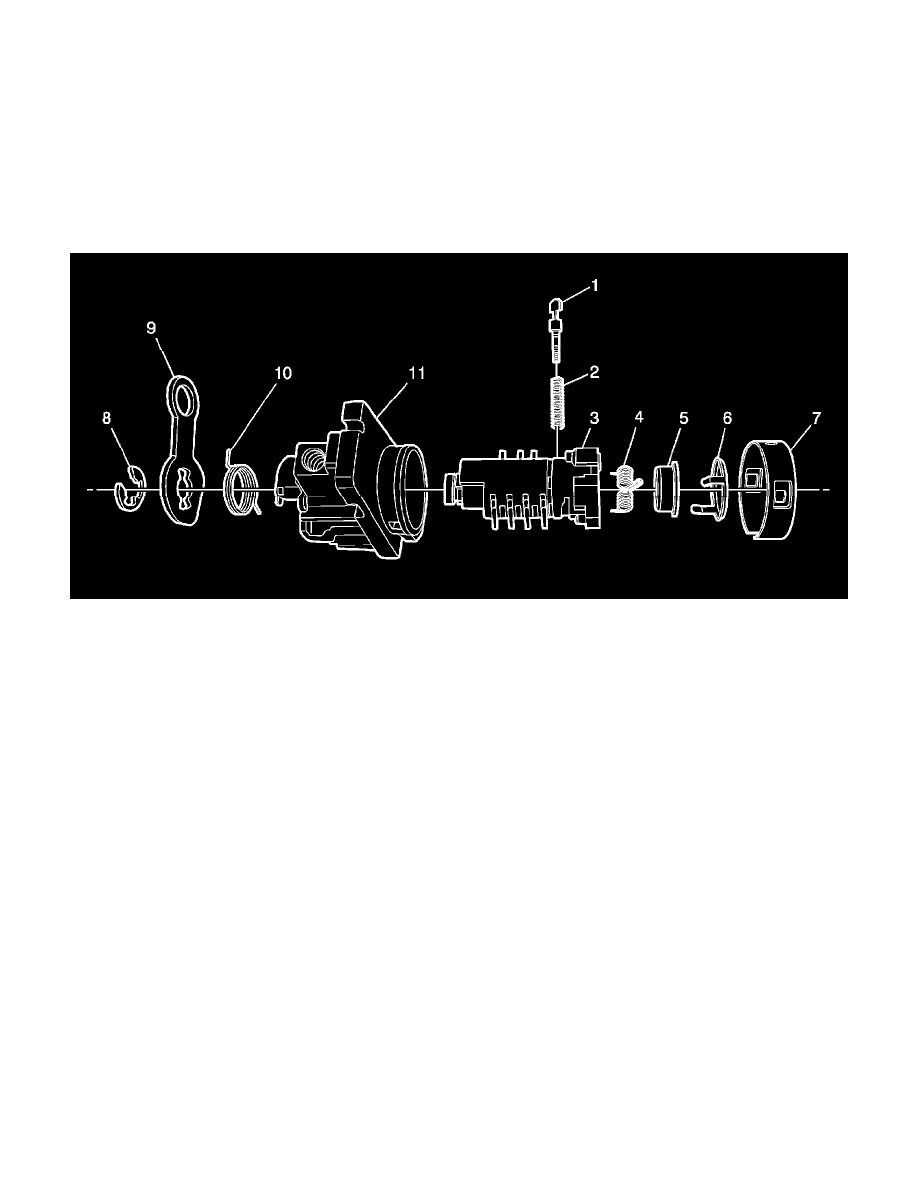
Door Lock Cylinder
The door lock cylinder uses 8 of the 10 key cut positions, 1-8 when counting from the key head. The tumbler orientations alternate in adjacent locations
from side to side with 4 tumblers on each side.
Note: The door lock cylinder tumblers (3) are not self-retaining and must be held in place if the key is not fully inserted into the lock cylinder or
until the lock cylinder (4) is assembled into the case assembly (1).
1. Hold the uncoded door lock cylinder (3) with the housing window facing up.
2. Insert one tumbler spring (2) into each of the 4 tumbler spring holes.
3. The first tumbler (1) to be loaded will be key cut position 2, the second number in the key code. Install this tumbler in the tumbler slot closest to
the head of the lock cylinder housing, the end where the key is inserted.
4. Advancing one tumbler slot at a time, install tumblers 4, 6, and 8 sequentially on the same side as tumbler 2.
5. Turn the lock cylinder over and insert one tumbler spring (2) into each of the 4 tumbler spring holes on the opposite side of the lock cylinder.
6. Insert tumbler 1 into the tumbler slot closest to the head of the lock cylinder housing (3), the end where the key is inserted.
7. Advancing one tumbler slot at a time, install tumblers 3, 5, and 7 sequentially on the same side as tumbler 1.
8. Check for correct tumbler loading by holding the tumblers (1) in position and inserting the correct key into the lock cylinder. All tumblers (1)
should be flush with the housing of the lock cylinder.
9. Lightly lubricate the tumblers and small detent recessed areas the tumblers are in with GM Super Lube GM P/N 12346241, or equivalent light
lithium grease.
10. Holding the tumblers in place, remove the key from the coded lock cylinder (3) and install the key door spring (4) with the center loop of the
spring facing the key slot.
11. Install the key door (5) and hold in the closed position while pushing the key door cover (6) onto the coded lock cylinder (3). The key door (5)
should be under tension from the key door spring (4), and the key door cover (6) tab will engage with the assembled lock cylinder (3), holding the
key door cover in place once installed.
12. Install the coded lock cylinder assembly into the door lock cylinder housing so the cut out area in the back of the lock cylinder assembly (3) lines
up with the cut out area in the back of the door lock cylinder housing (11).
13. Install the door lock cylinder housing cap (7) and crimp the cap into position in 2 areas at 1 o'clock and 7 o'clock when looking at the face of the
assembly in car position.
14. Install the return spring (10), inner winding end first, in the smaller notch in the lock cylinder housing (11).
15. Using a small flat-blade tool, pull the outer winding of the spring (10) clockwise until it engages with the larger notch in the lock cylinder housing
(11). Ensure the return spring is seated fully in the opening.