seat Workshop Repair Guides

SEAT Workshop Service and Repair Manuals

Repairing front wheel suspension > < Subframe: Assembly overview
Removal:
Removal:
  Note
t  Before beginning the removal of the subframe, ensure that the ignition key is not inserted in the ignition lock.
t  Disconnect the battery before beginning disassembly of the strut.
t  
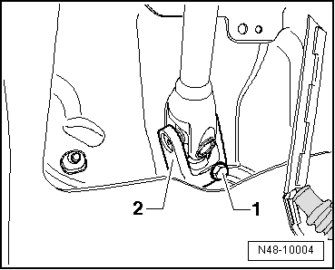
For those vehicles fitted with xenon dual-function headlights, the connection on the vehicle level sender must be unplugged before beginning the removal of the strut; this is located on the front left hand side suspension, depending upon version → Electrical system; Rep. gr. 94 .
t  Perform the basic setting of the lights → Electrical system; Rep. gr. 94 → Vehicle diagnostic tester.
t  Before beginning the removal of the strut support check the unloaded vehicle height off the ground, level → Chaptera- for its subsequent installation -.
t  Before beginning removal of the strut, the installation position on the bodywork must be secured for subsequent fitting. → Chapter
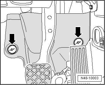
–  Ensure that the ignition key is not in the engine ignition lock.
–  Disconnect the battery → Electrical system; Rep. gr.27.
   
–  Unscrew nuts -arrows- and remove footwell trim.
  N48-10003
–  Undo bolt -1- and remove the cross member -2- from the steering box.
–  Raise the vehicle and remove the front wheels.
–  Remove the lower sound insulation → Bodywork, exterior installation work; Rep. gr.50 .
–  Detach the link rod from the stabiliser bar → Item.
–  Release the vehicle level sender sensor from the traverse swinging arm, located on the front left hand side suspension → Electrical system; Rep. gr. 94 .
–  Remove the exhaust system support from the strut.
  N48-10004
–  Remove bolts -arrows- from heat shield.
–  Remove heat shield from subframe.
  N48-10012
–  Unscrew the bolts -arrows- from the suspension ball joint.
–  Release the ball joint, along with the front suspension assembly, from the transverse swinging arm.
  Note
Before releasing the suspension ball joint from the steering knuckle: partially unscrew the nut to protect the thread, when the extractor is being used.
  N40-10005
–  Remove the ball joint from the stub axle using the Ball joint extractor -3287 A-.
  N48-10011
–  Release the pendulum support from the bolts -14- on the gearbox side.
–  Remove the bolts securing the exhaust pipe bracket to the strut.
  N40-10020
–  Unscrew the subframe cable protector -arrow-.
–  Disconnect all electrical connections on steering box.
l  Strut and consoles: secure the fitting position → Chapter.
  Note
The fastening devices -T10096- must be fitted to the positions -1, 8, 9 and 18 - alternately.
  N48-10013
–  Undo bolts -4 and 5- and slightly lower the drive assembly carrier with the consoles, steering box and stabiliser. Observe the electrical connections.
  N40-10020
–  Lower completely and carefully the strut using the motordriven lift -V.A.G 1383 A- with the base -T20145- and the counterhold -T20161 -.
–  Prepare the strut on a workbench in order to separate the steering box and the stabilizer bar.
–  Next, unscrew the bolts -10 and 17- securing the transversal swinging arms, to the console.
  E40-10026
–  Remove screws -2 and 7-, which connect the bearing bracket and the axle strut with the drive assembly carrier. The remove the axle strut from the drive assembly carrier.
–  Separate the steering box from the subframe by releasing the bolts -3 and 6-.
–  Separate the stabiliser bar from the subframe, releasing the bolts -11 and 16-.
  N40-10020

Repairing front wheel suspension > < Subframe: Assembly overview