
Leon Mk2
| Secondary shaft: Assembly overview |
 Note
Note| t | Whenever new pinions or new thrust rings are fitted, please consult the technical data and the → Electronic catalogue of spare parts„ETKA“. |
| t | Install all bearings, synchromeshed gears and synchro-rings on output shaft with gear oil. |
| t | Do not mix up synchromesh rings. If re-using, allocate them to corresponding mobile pinion. |
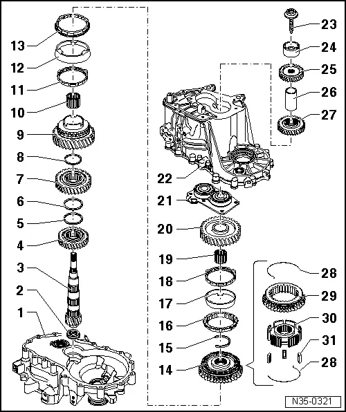
| 1 - | clutch housing |
| q | Repairing → Chapter |
| 2 - | Cylindrical roller bearing |
| q | With retaining ring |
| q | Remove → Fig. |
| q | Pressing in → Fig. |
| q | Installation position: once the bearing is fitted, the ring should point towards the secondary shaft |
| 3 - | Output shaft |
| q | If the roller bearing → Item is seated on an inner ring, the bearing can not be removed from the lay shaft |
| q | Check the seating or the inner cylindrical bearing ring for damage or scoring |
| q | If the seating or the inner cylindrical bearing ring shows scoring or damage then replace the secondary shaft and the cylindrical roller bearing |
| 4 - | Gear wheel for 4th gear |
| q | Installation position: The collar points towards the 3rd gear → Fig. |
| 5 - | Circlip |
| 6 - | Circlip |
| 7 - | 3rd gear wheel |
| q | Installation position: The collar points towards the 4th gear → Fig. |
| 8 - | Circlip |
| 9 - | Synchromeshed gear for 2nd gear |
| 10 - | Needle bearing |
| q | For 2nd gear |
| 11 - | Inner ring of 2nd gear |
| q | Check for wear → Fig. |
| q | Installation position → Fig. |
| 12 - | Outer ring of 2nd gear |
| q | Place above inner ring → Item |
| q | Renew if scored |
| q | Installation position → Fig. |
| 13 - | 2nd gear synchroniser ring |
| q | Check for wear → Fig. |
| q | Installation position → Fig. |
| 14 - | Locking collar with synchronising hub for 1st and 2nd gear |
| q | Press off together with 2nd speed selector gear after removing circlip → Item → Fig. |
| q | Dismantling → Fig. |
| q | Assembling locking collar/synchronising hub → Fig. and → Fig. |
| q | Installation position → Fig. |
| q | Pressing in → Fig. |
| 15 - | Circlip |
| q | Pressing off → Fig. |
| q | Fitting → Fig. |
| 16 - | Synchro-ring for 1st gear |
| q | Check for wear → Fig. |
| q | Fit so that the grooves insert in the locking elements of the mobile sleeve → Item |
| 17 - | Outer ring for 1st gear |
| q | Insert in synchro-ring → Item |
| q | Installation position → Fig. |
| q | Renew if scored |
| 18 - | Inner ring for 1st gear |
| q | Check for wear → Fig. |
| q | Check lugs for scoring |
| q | Installation position → Fig. |
| 19 - | Needle bearing |
| q | For 1st gear |
| 20 - | Synchromeshed gear for 1st gear |
| q | Installation position → Fig. |
| 21 - | bearing mounting with grooved ball bearing |
| q | Always replace the bearings with the allotment |
| q | Replace the allotment whenever it detaches from the gearbox casing |
| q | Pressing off → Fig. |
| q | Pressing in → Fig. |
| 22 - | Gearbox |
| q | Repairing → Chapter |
| 23 - | Bolt. |
| q | removing and fitting → Chapter |
| 24 - | Inner race of the cylindrical roller bearing |
| q | Mark before removal |
| q | Do not confuse with the inner ring of the input shaft roller bearing socket |
| q | These may be replaced individually |
| q | removing and fitting → Chapter |
| 25 - | Gear wheel for 6th gear |
| q | Installation position: the collar faces the sleeve |
| q | removing and fitting → Chapter |
| 26 - | Thrust piece |
| q | removing and fitting → Chapter |
| 27 - | 5th gear pinion |
| q | Installation position: the collar should be orientated towards the gearbox casing cover → Fig. |
| q | removing and fitting → Chapter |
| 28 - | Spring |
| q | Installation position → Fig. |
| 29 - | Mobile element |
| 30 - | Synchro-hub |
| 31 - | Locking pieces (3 off) |