seat Workshop Repair Guides

SEAT Workshop Service and Repair Manuals

Input shaft: adjustment > < Input shaft: Disassembling and assembling
Operation process
Operation process
  Note
t  Whenever new gears or shafts are mounted, always consult the technical data → Chapter.
t  If, as a result of parts replacement, the position of the roller bearing sockets is altered then the input shaft must be readjusted. Note the general adjustment overview → Chapter
   
Remove the outer track of the conical roller bearing
–  First remove guide bush → Chapter
  E35-0017
Install the outer track of the conical roller bearing
  E35-0018
Removing the roller bearing
  E35-0047
Install the roller bearing
  E35-0019
Remove the gear of the 4th gear, the conical roller bearing and the end washer with the needle bearing sleeve
–  Mount the adapter -U-40100/3- on the shaft on the gear pinion of the 4th gear.
The gear wheel of the 4th gear is removed together with the conical roller bearing, the end washer and the needle bearing sleeve.
  E35-0020
Removing the gear pinion for 3rd gear
–  Remove securing ring with pliers -A-81124-
  E35-0153
Installing the gear pinion for 3rd gear
Installation position:
the collar must be facing the 4th gear
–  Fit retaining ring.
  E35-0022
Installing the gear pinion for 4th gear
Installation position:
The selector collar must be orientated towards the gear pinion of 3rd gear.
  E35-0023
Install the roller bearing
–  Install adapter -U-40100/3- below the 2nd gear pinion, and position adapter -U-40200/19- side -A - orientated towards roller bearing.
  E35-0024
Fit the attack washer and the bush for gear needle roller bearing
–  Install adapter -U-40100/3- below the 2nd gear pinion, and position adapter -U-40300/8- with side -B- orientated towards needle bearing.
  E35-0025
Remove the outer track of the conical roller bearing
  E35-0026
Install the outer track of the conical roller bearing
  Note
If the input shaft has been adjusted, the shim must be fitted before assembling the outer track of the roller bearing
  E35-0027
For gearboxes manufactured from week 24/2006, the locking collar of 5th / 6th gears has a deep groove on both sides -arrows-.
  N34-10745
Dimension -a- (pointing to the side of 6th gear)For gearboxes manufactured up to week 24/2006For gearboxes manufactured from week 24/2006
 1.5 mm1.8 mm

   
Dimension -b- (pointing to the side of 5th gear)For gearboxes manufactured up to week 24/2006For gearboxes manufactured from week 24/2006
 1.5 mm2.0 mm

–  Allocate the locking collar and synchro-hub for 5th and 6th gears using the → Electronic spare parts catalogue „ETKA“.
Adjust the selector fork for 5th / 6th gear:
Adjust with gearboxes manufactured up to week 24/2006 → Fig.
Adjust with gearboxes manufactured from week 24/2006 → Fig.
   
Dismount and assemble mobile element and synchromesh body of 5th / 6th gear
1 - Elastic ring
2 - Locking piece
3 - Synchro-hub
4 - Mobile element
–  Slide locking collar over synchro-hub.
Deeper notches -arrow A- for locking pieces in synchro-hub and notches -arrow B- in locking collar must align.
  N35-0365
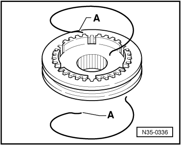
Insert the unit comprising locking collar and synchromesh body of 5th / 6th gear.
l  The mobile element is on the synchromesh body.
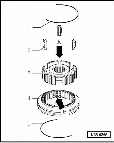
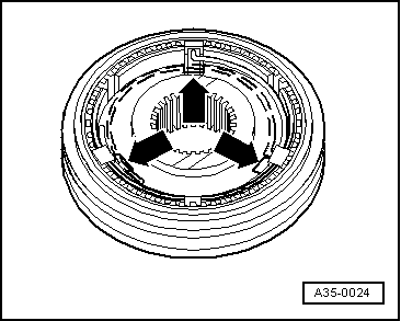
–  Fit the locking elements in the deepest grooves -arrows- and fit the elastic rings off-set by 120º. Angled end of spring washer must locate in hollow locking piece.
  Note
t  
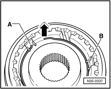
With those gearboxes manufactured from week 22/2008, a corrugated spring washer has been installed under the synchroniser ring for 5th gear and another, above the synchroniser ring for 6th gear, → Item and → Item.
t  For this reason, only install spring washers whose ends are not angled for the locking elements (as shown in → Fig., pos. 1-) 1-)
  A35-0024
Installing springs with bent ends -A-
These springs are installed on both sides.
–  Spring are installed only in conjunction with hollow locking pieces.
–  Insert threaded pieces.
  N35-0336
Installation location of the corrugated spring washers:
–  Insert the washers offset by 120°.
–  Angled end -A- of spring washer must locate in hollow locking piece.
The spring washer must be fitted under the protrusion -B- of locking pieces.
Bent ends always face away from synchro-hub -direction of arrow-.
  N35-0337

Input shaft: adjustment > < Input shaft: Disassembling and assembling