
Leon Mk2
| Dismantling and assembling output shaft for 3rd and 4th gear |
| Special tools and workshop equipment required |
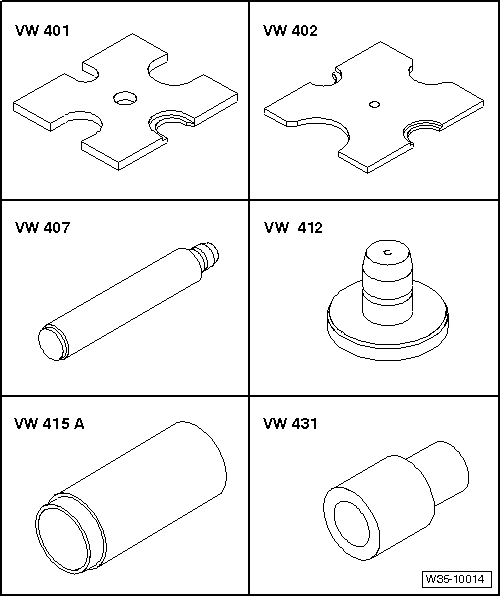
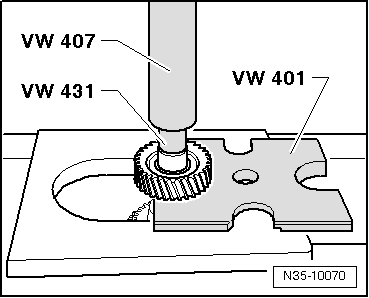
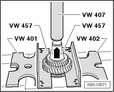
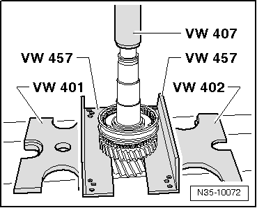
| t | Pressure plate -VW 401- |
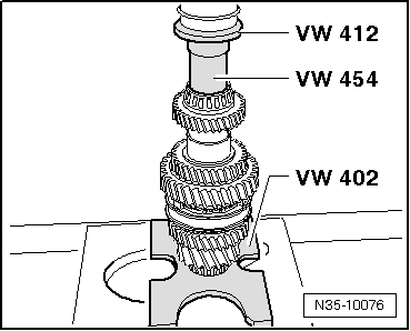
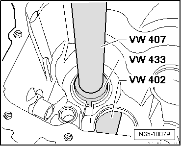
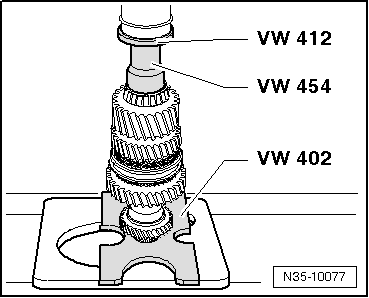
| t | Pressure plate -VW 402- |
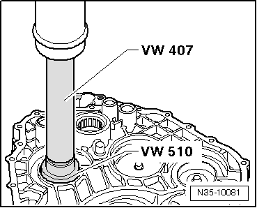
| t | Press die. -VW 407- |
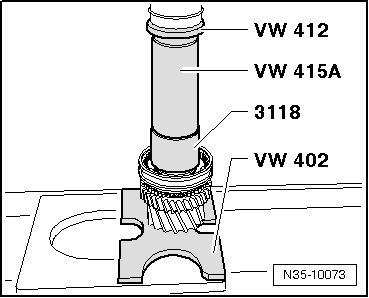
| t | Press die. -VW 412- |
| t | Tube -VW 415 A- |
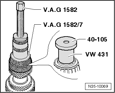
| t | Thrust piece -VW 431- |
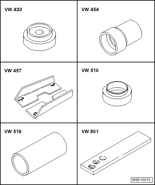
| t | Thrust piece -VW 433- |
| t | Thrust piece -VW 454- |
| t | Support rails -VW 457- |
| t | Thrust pad -VW 510- |
| t | Tube -VW 519- |
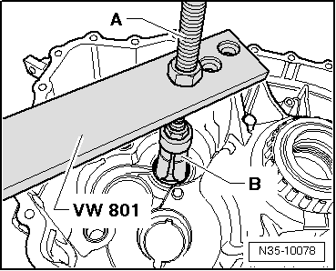
| t | Support plate -VW 801- |
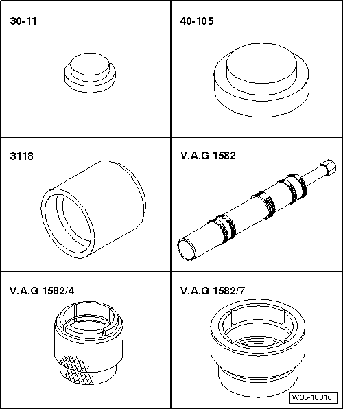
| t | Tightening plate -30 - 11- |
| t | Tightening plate -40 - 105- |
| t | Thrust piece -3118- |
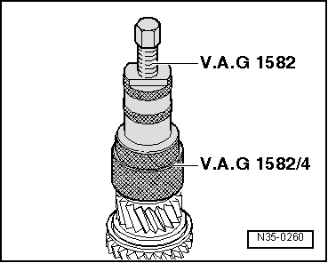
| t | Roller bearing bush extractor -V.A.G 1582- |
| t | Adapter -V.A.G 1582/4- |
| t | Adapter -V.A.G 1582/7- |
|
|
|
|
|
|
 Note
Note
|
|
|
|
|
|
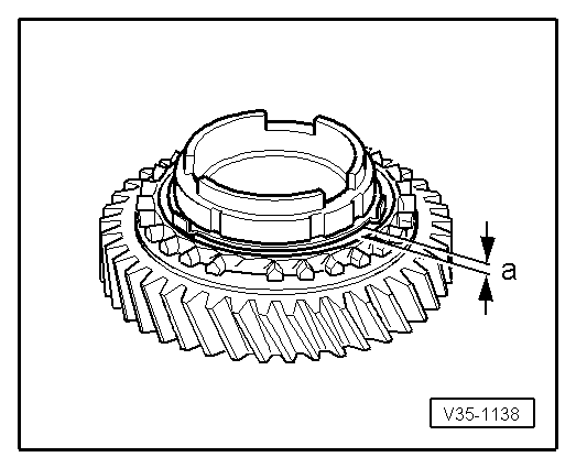
| Dimension -a- | Installation dimension | Wear limit |
| 3rd and 4th gears | 0.75 … 1.25 mm | 0.3 mm |
|
|
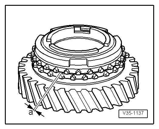
| Dimension -a- | Installation dimension | Wear limit |
| 3rd gear | 1.0 … 1.8 mm | 0.5 mm |
| 4th gear | 1.0 … 1.9 mm | 0.5 mm |
|
|
|
|
|
|
|
|
|
|
|
|
|
|
|
|
|
|
|
Note
|
|
Note
|
|
|
|
|
|
|
|
|
|
|
|
|
|