seat Workshop Repair Guides

SEAT Workshop Service and Repair Manuals

Specified torques > < Detaching
Installing
Installing
  Note
t  The special tools required can be obtained from the work sequence „removing and installing the gearbox“ → Chapter.
t  
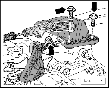
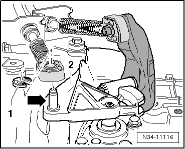
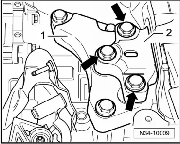
Renew self-locking nuts and bolts.
t  Renew the bolts tightened with specified tightening angle.
t  
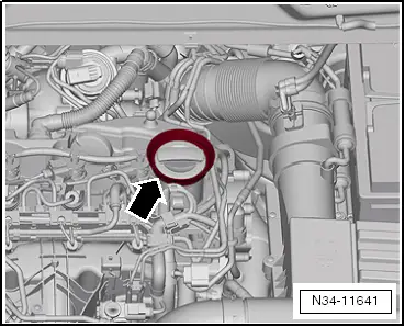
All cable ties which were opened or cut during removal must be renewed at the same points.
t  Clean input shaft splines and, on used clutch plate, hub splines. Remove corrosion and apply only a very thin coat of clutch plate spline grease -G 000 100- to splines. Then move the clutch plate on the input shaft from side to side, until the hub moves smoothly on the shaft. Excess grease must be removed.
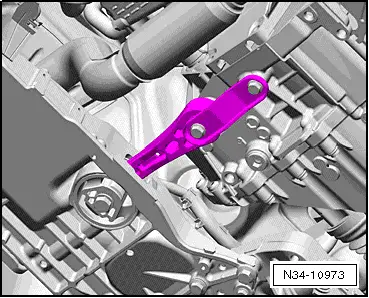
–  If the gearbox is to be renewed, transfer the gearbox selector lever and relay lever to the new gearbox.
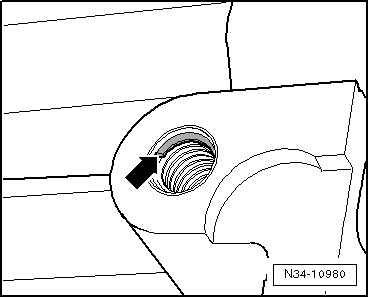
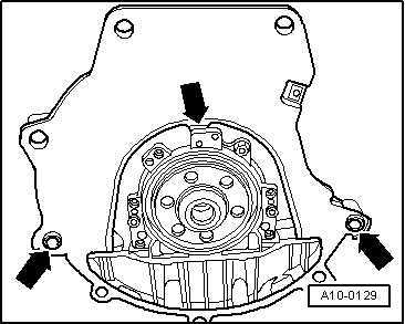
–  Carefully use thread tap to remove any remaining locking fluid from all threaded holes which will accommodate self-locking bolts.
–  Clean splines of input shaft and apply a thin coat of grease for clutch plate splines -G 000 100-.
The clutch plate must slide easily to and fro on the input shaft.
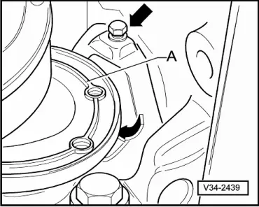
–  Check whether dowel sleeves for centring the engine/gearbox assembly are fitted in the cylinder block; install if necessary.
If the dowel sleeves are not fitted, this will lead to gear-change problems, clutch malfunction and in some cases gearbox noise (gears will make rattling noises).
   
–  Observe that the intermediate plate is fitted on sealing flange and is slid onto the dowel sleeves -arrows-.
–  Check release bearing for wear; if necessary, renew slave cylinder with release bearing → Chapter.
–  Fit the previous assembly onto the hydraulic jack -SAT 1040- and place it in installation position.
  Note
When lifting the gearbox, care should be taken not to damage any cables and pipes.
–  If necessary, turn gearbox further upwards near differential using spindles of gearbox braket -T20138C-.
  A10-0129
–  Then carefully raise gearbox further, observing longitudinal member -arrows-.
–  If necessary, tilt gearbox further using spindles of gearbox bracket -T20138C-.
–  Guide gearbox with differential over subframe -A-.
  N34-10996
–  If necessary, turn gearbox further upwards near differential using spindles of gearbox braket -T20138C-.
  N34-11150
l  Then the right flange shaft must be guided past the flywheel -arrow 2- and the notch in the intermediate plate -arrow 1-.
–  Place intermediate plate onto dowel sleeves on engine if necessary.
–  Align the gearbox to the engine and fit.
–  Then rotate the gearbox via the counterhold -T20138C- spindle until it is in installation position.
–  Align gearbox on engine dowel sleeves and join.
–  Screw in lower engine/gearbox securing bolts and tighten to specified torque → Chapter.
–  Once the gearbox is screwed to the engine underneath, remove the gearbox support -T20138C- from the gearbox.
–  Screw in upper engine/gearbox securing bolts and tighten to specified torque → Chapter.
–  Attach gearbox selector lever to selector shaft of gearbox → Fig. and tighten hexagon nut to specified torque → Item.
–  Install relay lever together with cable end-piece → Chapter.
  N34-11149
–  Install bracket -1- on gearbox using new hexagonal bolts -arrows- and tighten to specified torque → Chapter.
  N34-10010
–  Align engine and gearbox in installation position. To do so, raise engine/gearbox until gearbox bracket -1- makes full contact with gearbox mounting (left) -2-.
–  Screw new hexagon bolts -arrows- for left assembly mounting -2- into bracket -1- and tighten to specified torque → Chapter.
  Note
Install engine/gearbox mountings stress-free → Rep. gr.10.
  WARNING
Only remove the gearbox bracket -T20138C- once the respective tightening torque has been applied to all fixing screws of the subframe.
  N34-10009
–  If small cover plate -A- for flywheel is present, install it -arrows- → Chapter.
  Note
  V34-2439
t  There are threaded inserts, e.g. „HeliCoil“ in the bolting holes for the pendulum support.
t  Distinguishing feature: Groove on the first thread pitch -arrow-.
t  Note the fixing screw and the respective tightening torque → Running gear, axles, steering; Rep. gr.40
  N34-10980
–  Remove the pendulum support → Running gear, axles, steering; Rep. gr.40.
–  Then install drive shafts → Running gear, axles, steering; Rep. gr.40.
  N34-10973
–  Install drive shaft heat shield, if present -arrows- → Running gear, axles, steering; Rep. gr.40.
  N34-11369
–  Attach the coupling rod to the anti-roll bar -1- → Running gear, axles, steering ; Rep. gr.40.
  N34-11344
–  If the front left vehicle level sender -G78- is installed, screw it to the transverse link → Rep. gr.40.
  N34-11241
–  Connect the connector -1- to the oil level and temperature sender -G266-.
–  Assemble exhaust system → Rep. gr.26.
  N34-10504
–  Install cowling -arrow- together with radiator fans → Rep. gr.19.
  N34-11165
–  Install right and left charge air hose -arrow 1- → Rep. gr.21.
–  Then install starter and secure with lower bolt → Electrical system; Rep. gr.27.
–  Secure wiring retainer to lower starter bolt.
–  Install upper starter bolt; attach connector and wiring to starter → Electrical system; Rep. gr.27.
  N19-10337
–  Attach earth strap -1- to upper starter bolt.
–  Push connector -2- onto reversing light switch -F4-.
  N34-10003
–  Gearbox for vehicles with start stop system Plug on the connector -arrow- to the gearbox neutral position sender -G701-.
–  Push pipe/hose line or pipe line -A- to stop into slave cylinder breather and press down clip -arrow-.
  N34-11322
–  Test line by tugging on it.
–  Hydraulic clutch system: bleeding of air → Chapter.
–  Check for correct installation position of vacuum hose for brake system, install vacuum hose if necessary → Rep. gr.47.
  N34-10997
–  Install selector cable support bracket on gearbox and tighten bolts and nut -arrows- to specified torque → Item.
–  Insert gate selector cable in cable end-piece.
  N34-11117
–  Spread a small amount of grease on pin -arrow- of gearbox selector lever -2-.
Allocate grease using → Electronic parts catalogue (ETKA).
–  Renew securing clip -1- each time it is removed.
–  Adjust selector mechanism → Chapter.
–  Install battery tray and battery → Electrical system; Rep. gr.27
–  Install complete air filter housing → Rep. gr.23 or → Rep. gr.24.
  N34-11116
–  Then press on grommet -arrow-.
–  Fit the cover on the engine.
–  Connect battery and follow procedure after connecting battery → Electrical system; Rep. gr.27.
–  Mount plenum chamber cover → Body; Rep. gr.50
–  Mount windscreen wiper arms → Electrical system; Rep. gr.92.
–  Check gear oil → Chapter.
–  Install front left wheel housing liner → General body repairs, exterior; Rep. gr.66.
–  Install noise insulation → General body repairs, exterior; Rep. gr.50.
–  For vehicles with front left sender for vehicle level -G78-, the headlight adjustment has to be checked → Electrical system; Rep. gr.94.
  N34-11641

Specified torques > < Detaching