
Leon Mk2
|
|
|
|
|
 Note
Note
|
|
Note |
|
|
|
|
|
|
|
|
|
Note
|
|
|
|
Note
|
|
Note
Note
|
|
|
|
|
|
|
|
|
|
|
|
|
|
|
|
Note
|
|
Note
|
|
|
|
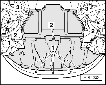
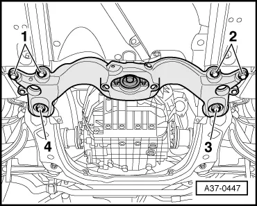
| Component | Nm |
| Bracket of the operating cable on the gearbox | 23 |
| Bolts M12 in position -3 and 4- of the gearbox cross-member | 110 + 90° → Remark |
| Bolts M10 in position -1 and 2- of the gearbox cross-member | 65 |
|