
Leon Mk2
|
 Note
Note| Lubricate the support points and contact surfaces with polyurea grease. Allocation: → Spare parts catalogue. |
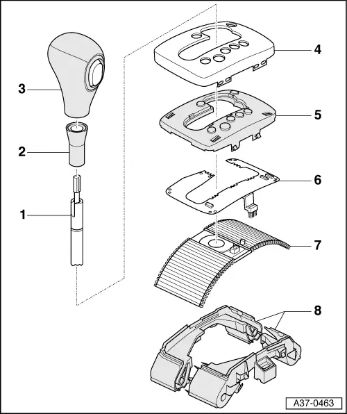
| 1 - | Gate selector lever |
| 2 - | Selector lever trim |
| q | Removing and installing → Chapter>>>>>>>> |
| 3 - | Selector lever handle |
| q | Removing and installing → Chapter>>>>>>>> |
| 4 - | Cover |
| q | With selector range and Tiptronic mode |
| q | Removing and installing → Chapter and in addition unclip symbol insert |
| 5 - | Symbol insert |
| q | Is attached to the cover. |
| 6 - | Plate conductor |
| q | With integrated Tiptronic switch -F189- |
| q | Removing and installing → Chapter>>>>>>>> |
| q | The switch comprises 3 Hall sensors, which are activated by a magnet on the transverse slide of the sliding cover. |
| q | In the event of faults, first check that magnet is properly secured on transverse slide of sliding cover → Item and renew sliding cover if necessary. |
| q | Before renewing printed circuit board when fault memory indicates fault code „18161“, first check adjustment of selector lever cable → Chapter |
| 7 - | Sliding cover |
| q | With solenoid for the Tiptronic switch -F189- in the transverse slide |
| q | Removing and installing → Chapter>>>>>>>> |
| 8 - | Guide for sliding cover |
| q | Carefully pry apart the two halves |