seat Workshop Repair Guides

SEAT Workshop Service and Repair Manuals

Mechatronic unit for the semi-automatic gearbox J743 : Removing and installing (with gearbox removed) > < Mecatronic unit for the asemi-automatic gearboxJ743 : dismounting
Mecatronic unit for the semi-automatic gearboxJ743 : Install
Mecatronic unit for the semi-automatic gearbox -J743 -: Install
Before touching mechatronic unit, touch an earthed object → Anchor.
Installation is carried out in the reverse sequence; note the following:
   
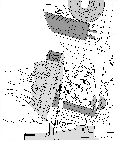
–  Place the mechatronic control unit -J743- on the gearbox casing carefully.
  Note
t  The side cover should not be removed in order to remove other parts
t  For reasons of illustration, the cover on the side has been removed in the figure.
–  Do not pinch wiring.
Take care not to trap the cable.
–  Carefully set mechatronic unit on dowel pins -arrow-. Ensure that »sender arm« locates in its -fitting position-.
–  Look to see if mechatronic unit has made contact correctly.
  N34-10526
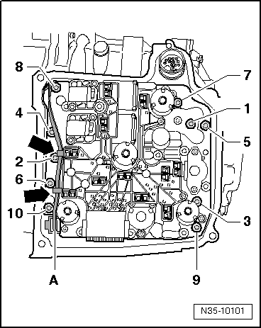
–  Screw in new bolts -1- through -10- hand-tight.
–  Tighten bolts in given order to 5 Nm + 90° (1/4 turn).
–  Hook line -A- first in upper retaining lug, and then in lower -arrows-.
–  Push on connector and engage.
  N35-10101
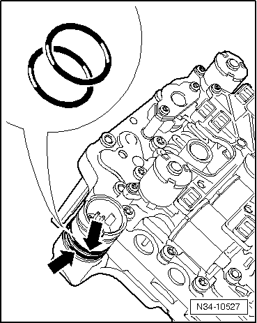
–  Replace the two -O-rings- if the »old« mechatronic control unit is to be reassembled.
–  Lubricate the O-rings with gearbox oil for DSG dual clutch.
–  Clean cover seal and sealing surfaces on gearbox.
–  Ensure proper seating of seal.
–  Put the cover on the mechatronics. Do not attach any tubes in doing so.
  N34-10527
–  Insert new bolts -arrows- and tighten diagonally in several stages to 10 Nm.
–  Push on connector for mechatronic unit for dual clutch gearbox -J743- and engage lock by turning.
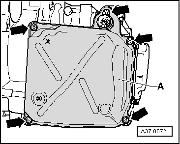
  A37-0672
–  Set new oil pump cover -A- in place and tighten bolts -arrows- diagonally in several stages to 8 Nm.
–  Attach wire retainer to cover and tighten nuts to 10 Nm.
–  Push on connector for mechatronic unit for dual clutch gearbox -J743- and engage lock by turning.
–  If fitted, fit the hose joining the intercooler and the booster air pipe → Rep. gr.21.
–  Reinstall any parts which may have been removed from the vehicle.
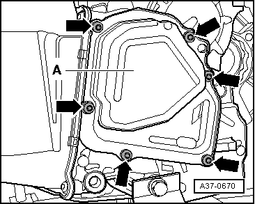
  A37-0670
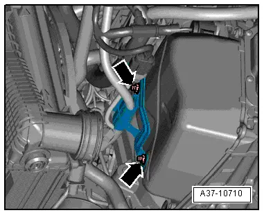
–  Fit the cable support on the large cover and tighten the nuts to a torque of 10 Nm.
–  Reinstall any parts which may have been removed from the vehicle.
–  Connect the battery earth strap → Electrical system; Rep. gr. 27
  A37-10710
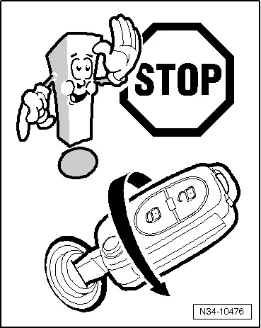
–  Do not start the engine.
–  Please renew filter if oil is contaminated → Chapter.
–  Connect → Vehicle diagnostic tester.
–  Fit the oil tray -SAT 1100- under the drain plug of the gearbox.
  N34-10476
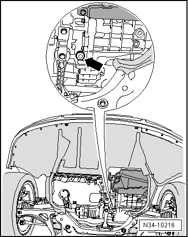
–  Remove oil drain plug close to pendulum support -arrow-.
  N34-10216
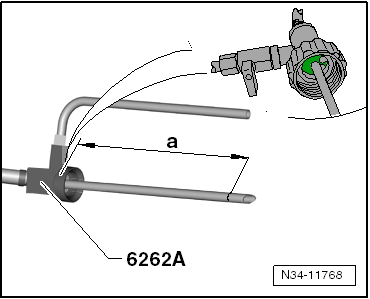
–  Before screwing adapter for oil filling -VAS 6262 A- onto oil bottle, measure length of breather pipe, dimension -a- and shorten → Anchor.
Dimension -a- = 210 mm
  Note
The dimension -a- is measured from the shaft (green area in the counting glass) of the adapter for oil filling -VAS 6262 A-.
  N34-11768
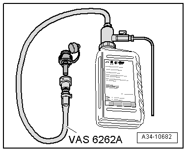
–  Screw the adapter for filling -VAS 6262 A- hand tight into the inspection hole.
  A34-10682
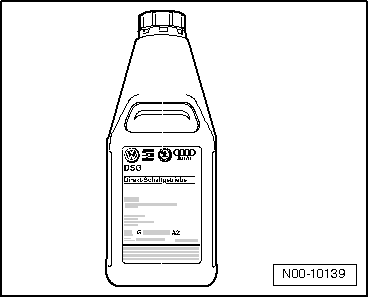
–  Shake bottles before opening.
–  Fill 3 litres of oil.
–  To change the bottle, the valve must be closed or the adapter for the oil filling -VAS 6262 A- must be held above the gearbox.
Next, start engine, check oil level and top up oil. The adapter for the oil filling -VAS 6262 A- must remain installed.
–  Check the oil level and top-up if necessary → Chapter.
–  Mount the noise insulation element → Bodywork, exterior installation work; Rep. gr.50.
–  Make the basic adjustment using the central diagnosis -VAS 505X-.
  N00-10139

Mechatronic unit for the semi-automatic gearbox J743 : Removing and installing (with gearbox removed) > < Mecatronic unit for the asemi-automatic gearboxJ743 : dismounting