
Testing fuel pump relay J17 for Fabia Mk1 Drive Unit
|
|
|
|
|
|
|
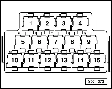
| Relay carrier in left driver's footwell, plug location, contact | Test box -V.A.G 1598/31- contact | |
| ► 01.00 | 1 | 80 |
| 02.00 ► | 5 | 80 |
|
|
|
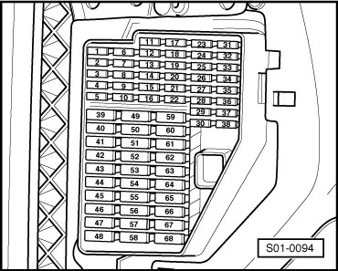
| Retaining clip | Nominal value on one of the contacts | |
| 9 | approx. battery voltage | |
| 24 | approx. battery voltage | |
| 35 | approx. battery voltage | |
| 61 | approx. battery voltage |
|