skoda Workshop Repair Guides

Skoda Workshop Service and Repair Manuals

Vehicle electrics > < Setting overview for gearbox as of gearbox manufacturing date 07.03
Adjusting the differential gear
Special tools and workshop equipment required
t  Gauge block plate -MP3-405/17 (VW 385/17)-
t  Pressure plate -MP3-407 (VW 402)-
t  Thrust piece -MP3-408 (VW 412)-
t  Universal dial gauge holder -MP3-447 (VW 387)-
t  Thrust piece -MP3-448 (VW 408A)-
t  Pressure plate -MP3-458/1 (VW 472/1)-
t  Pipe -MP6-419 (3259)-
t  Gearbox mount -T30012-
t  Pipe -T30019 (3345)-
t  Thrust plate -T30045 (3005)-
t  Interior extractor 46...58 mm e.g. -Kukko 21/7-
t  Countersupport e.g. -Kukko 22/2 -
t  Torque wrench
t  Dial gauge
The differential gear must be re-set when the following components are replaced:
t  Gearbox housing
t  Clutch housing
t  Differential housing
t  differential gear tapered-roller bearing
Setting overview → Chapter.
   
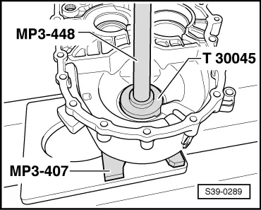
–  Press the outer ring/tapered-roller bearing with washer in the clutch housing.
  Note
Pay attention to the fitting position of the washer for gearboxes as of gearbox manufacturing date 07.03. The shoulder on the inside diameter points towards the gasket ring.
  S39-0289
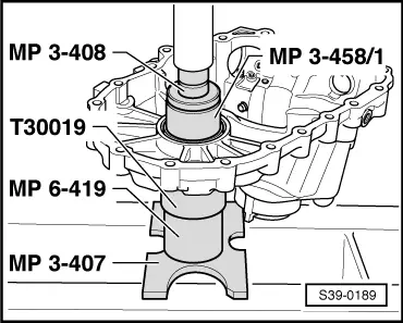
–  Press outer ring/tapered-roller bearing without adjusting washer into the gearbox housing.
–  Support the gearbox housing with a pipe -T30019- directly below the bearing support.
  Note
Instead of pressure plate -MP3-458/1- it is also possible to use thrust plate -T30045-.
–  Insert the differential gear in the clutch housing.
–  Position the gearbox housing and tighten 5 screws to the given tightening torque → Chapter or → Chapter.
–  Press differential gear towards the clutch housing while simultaneously turning eight times.
–  Press differential gear towards the gearbox housing while simultaneously turning eight times.
  S39-0189
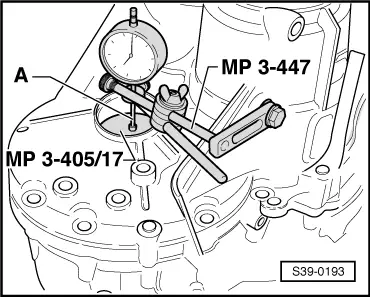
–  Set the dial gauge to 0 with 1 mm preload on “0”.
A - Dial gauge extension 30 mm
–  Move the differential shaft up and down, read off and write down the clearance on the dial gauge (example: 0.70 mm).
Determine the adjusting washer
The prescribed bearing preload is reached by adding to the established measured value a constant compression value (0.25 mm).
Example:
  S39-0193
measured value0.70 mm
+ pressure (const. value)0.25 mm
Thickness of the adjusting washer =0.95 mm

–  Remove the gearbox housing.
   
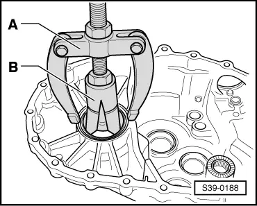
–  Remove outer ring/tapered-roller bearing from the gearbox housing.
A - Countersupport, e.g. -Kukko 22/2-
B - Interior extractor 46...58 mm, e.g. -Kukko 21/7-
–  Insert an adjusting washer of the correct thickness.
The following adjusting washers are available:
  S39-0188
Thickness (mm)Spare part No.
0,65
0,70
0,75
02B 409 210
02B 409 210 A
02B 409 210 B
0,80
0,85
0,90
02B 409 210 C
02B 409 210 D
02B 409 210 E
0,95
1,00
1,05
02B 409 210 F
02B 409 210 G
02B 409 210 H
1,10
1,15
1,20
02B 409 210 J
02B 409 210 K
02B 409 210 L
1,2502B 409 210 M

If the measured washer thickness is greater than the one listed in the table, 2 washers corresponding to the measured value may be fitted. First insert the thicker adjusting washer.
Different tolerances allow to measure the required thickness for each washer very precisely.
   
–  Press outer ring in again and tighten the gearbox housing with tightening torque → Chapter or → Chapter.
  S39-0189

Vehicle electrics > < Setting overview for gearbox as of gearbox manufacturing date 07.03