
Fabia Mk2
|
|
|
|
|
|
|
|
|
|
|
 Note
Note
|
|
|
|
|
|
|
|
Note
|
|
 Caution
| Tightening torques: |
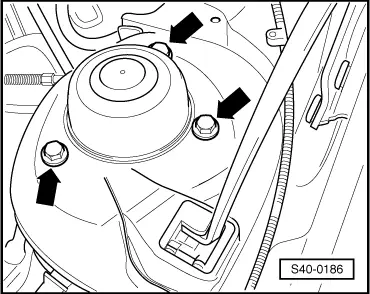
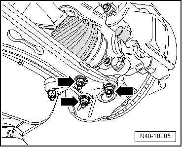
Suspension strut to body
| 15 Nm + 90° | ||||
Wheel-bearing housing to suspension strut
| 60 Nm + 90° | ||||
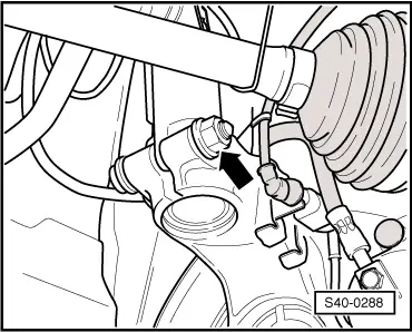
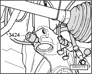
Track rod end/track rod to steering arm
| 20 Nm + 90° | ||||
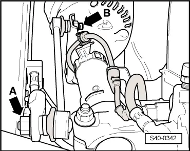
| Coupling rod to suspension strut | 40 Nm | ||||
Twelve-point nut for securing the drive shaft to wheel hub
| 50 Nm + 45° | ||||
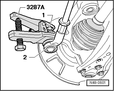
Steering joint to track control arm
| 40 Nm + 45° | ||||
| Wheel bolts | → Chapter |