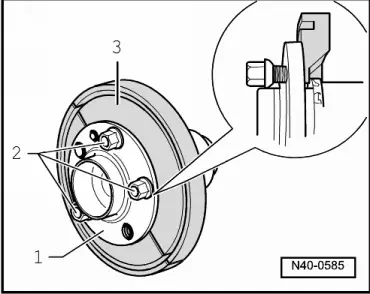
| Cover plate to wheel-bearing housing | 10 Nm |
| Phillips head screw of brake disc to wheel hub with wheel bearing | 4 Nm |
Twelve-point nut for securing the drive shaft to wheel hub| t
| Do not grease thread of the outer joint of the drive shaft. |
| 50 Nm + 45° |
| Track rod/track rod end to steering arm | 20 Nm + 90° |
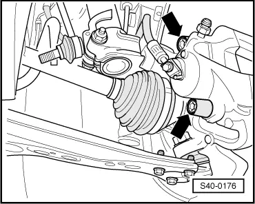
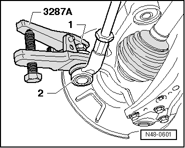
| Steering joint to track control arm | 20 Nm + 90° |
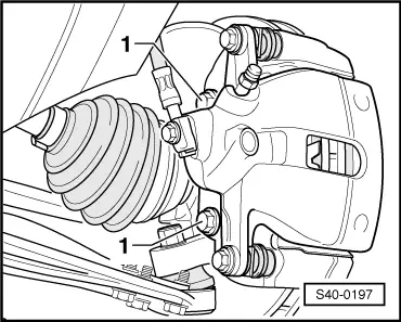
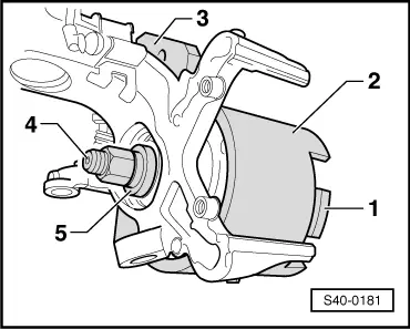
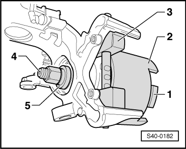
| FS-III brake caliper to wheel bearing housing | 28 Nm |
| Brake carrier with C54 brake caliper to wheel bearing housing | 125 Nm |
| ABS speed sensor to wheel-bearing housing | 8 Nm |
| Coupling rod to anti-roll bar | 40 Nm |
| Wheel bolts | → Chapter |

 Note
Note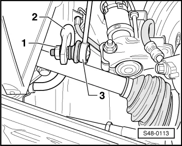
 Caution