
Fabia Mk2
|
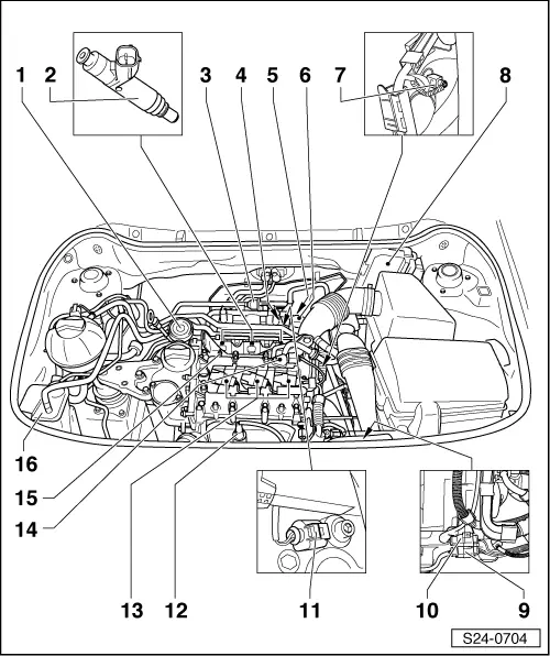
| For engine with identification characters BME |

| 1 - | Activated charcoal filter solenoid valve 1 -N80- |
| q | resistance: 22…30 Ω |
| 2 - | The vacuum regulating valve (PCV valve) |
| q | for crankcase ventilation |
| q | Pay attention to the part number |
| 3 - | Injection valves -N30…N32- |
| q | resistance: 12…17 Ω (at approx. 20 °C) |
| q | Inspecting the injection rate, tightness and jet formation of the injectors → Chapter |
| q | Summary of components → Chapter |
| 4 - | Engine speed sender -G28- |
| q | Fitting location: at cylinder block suction side |
| 5 - | Intake manifold pressure sender -G71- and Intake manifold temperature sender -G72- |
| q | Fitting location: at intake manifold |
| 6 - | Throttle valve control unit -J338- |
| 7 - | Coolant temperature sender -G62- |
| 8 - | Engine control unit |
| q | Control unit Simos -J623- |
| 9 - | 4-pin plug |
| q | Brown |
| q | for lambda probe downstream of catalytic converter -G130- and heater of lambda probe 1 downstream of catalytic converter - Z29- |
| 10 - | 4-pin plug |
| q | black |
| q | for lambda probe upstream of catalytic converter -G39- and heater for lambda probe upstream of catalytic converter - Z19- |
| 11 - | Knock sensor I - G61- |
| q | Fitting location: at cylinder block suction side |
| 12 - | Lambda probe upstream of catalytic converter - G39-, 50 Nm |
| q | Fitting location: in the exhaust manifold |
| 13 - | Ignition coils with power output stage -N70-, -N127-, -N291- |
| q | check → Vehicle diagnosis, testing and information system VAS 5051 |
| q | resistances → Chapter |
| q | removing → Chapter |
| 14 - | Camshaft position sensor -G163- |
| 15 - | Earth point -19- |
| q | on the cylinder head cover |
| 16 - | Activated charcoal filter |
| q | Vehicles ? 03.10 |
| For engine with identification characters BZG, CGPA |
| 1 - | The vacuum regulating valve (PCV valve) |
| q | for crankcase ventilation |
| q | Pay attention to the part number |
| 2 - | Injection valves -N30…N32- |
| q | resistance: 12…17 Ω (at approx. 20 °C) |
| q | Inspecting the injection rate, tightness and jet formation of the injectors → Chapter |
| q | Summary of components → Chapter |
| 3 - | Activated charcoal filter solenoid valve 1 -N80- |
| q | resistance: 22…30 Ω |
| 4 - | Engine speed sender -G28- |
| q | Fitting location: at cylinder block suction side |
| 5 - | Intake manifold pressure sender -G71- and Intake manifold temperature sender -G72- |
| q | Fitting location: at intake manifold |
| 6 - | Throttle valve control unit -J338- |
| 7 - | Coolant temperature sender -G62- |
| 8 - | Engine control unit |
| q | Control unit Simos -J623- |
| 9 - | 4-pin plug |
| q | Brown |
| q | for lambda probe downstream of catalytic converter -G130- and heater of lambda probe 1 downstream of catalytic converter - Z29- |
| 10 - | Connector |
| q | black for lambda probe upstream of catalytic converter - G39- and heater for lambda probe upstream of catalytic converter -Z19- |
| q | 4-pin |
| 11 - | Knock sensor I - G61- |
| q | Fitting location: at cylinder block suction side |
| 12 - | Lambda probe upstream of catalytic converter - G39-, 50 Nm |
| q | Fitting location: in the exhaust manifold |
| 13 - | Ignition coils with power output stage -N70-, -N127-, -N291- |
| q | check → Vehicle diagnosis, testing and information system VAS 5051 |
| q | resistances → Chapter |
| q | removing → Chapter |
| 14 - | Camshaft position sensor -G163- |
| 15 - | Earth point -19- |
| q | on the cylinder head cover |
| 16 - | Activated charcoal filter |
|
|