
Fabia Mk2
|
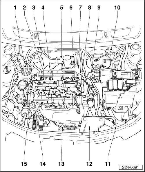
| A - | Accelerator pedal position sender -G79- and accelerator pedal position sender 2 -G185- |
| q | in footwell on the accelerator pedal (both senders integrated into a housing) |
| B - | lambda probe downstream of catalytic converter -G130- |
| q | downstream of main catalytic converter → Chapter |
| 1 - | The vacuum regulating valve (PCV valve) |
| q | at timing case → Chapter |
| 2 - | Injection valves |
| q | Injection valve for cylinder 1 -N30- |
| q | Injection valve for cylinder 2 -N31- |
| q | Injection valve for cylinder 3 -N32- |
| q | Injection valve for cylinder 4 -N33- |
| q | at fuel distributor |
| q | removing and installing → Chapter |
| 3 - | Intake manifold pressure sender -G71- and intake air temperature sender -G42- |
| q | on the intake manifold → Item |
| 4 - | Knock sensor 1 -G61- |
| q | at rear cylinder block |
| q | removing and installing → Chapter |
| 5 - | Solenoid valve 1 for activated charcoal filter -N80- |
| q | on the intake manifold → Item |
| 6 - | Throttle valve control unit -J338- |
| q | with throttle valve drive for electronic power control -G186-, angle sensor 1 for throttle valve drive for electronic power control -G187- and angle sensor 2 for throttle valve drive for electronic power control -G188- |
| q | on the intake manifold → Item |
| 7 - | Engine speed sender -G28- |
| q | at rear crankshaft sealing flange, suction side |
| 8 - | Hall sender -G40- |
| q | at camshaft housing → Chapter |
| 9 - | Coolant temperature sender -G62- |
| q | in coolant regulator housing → Chapter |
| 10 - | Motronic engine control unit -J623- with atmospheric charge pressure sender |
| q | removing and installing → Chapter |
| 11 - | Thermoswitch for radiator fan -F18- |
| q | at bottom left coolant fitting → Chapter |
| 12 - | 4-pin plug |
| q | for lambda probe -G39- and lambda probe heating before catalyst |
| q | at plug holder at starter |
| 13 - | Lambda probe -G39- |
| q | in front of the catalytic converter → Chapter |
| 14 - | Ignition coils with a power output stage |
| q | Ignition coil 1 with a power output stage -N70- |
| q | Ignition coil 2 with a power output stage -N127- |
| q | Ignition coil 3 with a power output stage -N291- |
| q | Ignition coil 4 with a power output stage -N292- |
| q | removing and installing → Chapter |
| 15 - | Camshaft adjustment valve 1 -N205- |
| q | for engine with identification characters BTS |