skoda Workshop Repair Guides

Skoda Workshop Service and Repair Manuals

Removing and installing Hall senderG40 > < Removing
Install
Install
  Note
t  There must not be any oil or coolant present in the blind holes for the cylinder head bolts.
t  Replace cylinder head bolts.
t  When undertaking assembly replace self-locking nuts and screws as well as gasket rings and gaskets which have been tightened to a torquing angle.
t  Remove the new cylinder head gasket from its wrapping immediately before fitting.
t  Treat the seal with the utmost care. Damage to the silicone layer and in the area of the bead results in leakages.
t  When installing an exchange cylinder head with the camshafts installed, it is necessary to oil the contact surfaces between the roller arms and the cams after installing the cylinder head.
t  Secure all hose connections with corresponding hose clips.
  WARNING
Wear protective gloves and goggles when working with gasket remover and degreasing agent!
–  Make sure that when cleaning the cylinder head and cylinder block no foreign bodies can get into the cylinder or into the oil and coolant galleries.
–  Carefully remove old sealant residue from the cylinder head and cylinder block using a chemical sealant remover.
–  Remove the crankshaft arrester -T10050- before fitting on the cylinder head and turn back the crankshaft in the opposite direction of rotation of the engine until all the pistons are almost evenly at TDC.
   
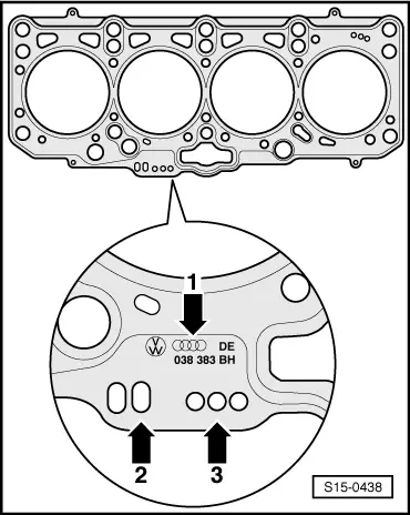
–  Pay attention to the identification of the cylinder head seal.
t  Part number = -arrow 1-
t  Bores -arrow 2- (ignore)
t  Bores = -arrow 3-
  Note
t  Install a new cylinder head gasket with the same marking, irrespective of whether or not the cylinder head was replaced.
t  If parts of the crankshaft drive were replaced, then the new cylinder head gasket must be redefined by measuring the protrusion of the piston in TDC.
–  Position the cylinder head gasket with the marking to the top.
  S15-0438
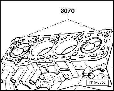
–  For centering, screw in guide bolts -3070- into the outer holes on the suction side.
  Note
The tensioning roller must be fitted onto the pin screws when placing on the cylinder head.
–  Fit on cylinder head, insert all 8 cylinder head bolts and tighten by hand.
–  Remove the guide bolt by screwing out with a bolt tightener from -3070- through the screw holes and insert the cylinder head screws.
  N15-0255
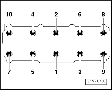
–  Tighten the cylinder head in four stages in the indicated tightening sequence:
  V15-0738
StageTighten
I
–  Pre-tighten with the torque wrench to 35 Nm.
II
–  Pre-tighten with the torque wrench to 60 Nm.
III
–  Using a rigid wrench torque a further 90° (1/4 turn).
IV
–  Using a rigid wrench torque a further 90° (1/4 turn).

  Note
Tightening up the cylinder head bolts after doing repair work is not necessary.
Further installation occurs in reverse order, while paying attention to the following:
–  The tightening torques which are missing can be found in the corresponding explosion view drawing.
–  Filling and bleeding the fuel system. For this purpose, connect the vehicle diagnosis, measurement and information system -VAS 505x- and carry out the targeted function „bleeding the fuel system“. During this function, the fuel pump is actuated for 180 seconds.
–  Check fuel system for tightness → Chapter.
–  Perform a test drive and interrogate fault memory and erase → Vehicle diagnostic tester.
  Note
After deleting the fault memory of the engine control unit the readiness code must be re-generated.
   

Removing and installing Hall senderG40 > < Removing