| –
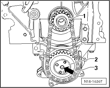
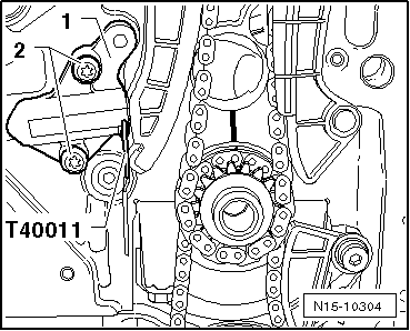
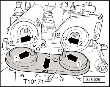
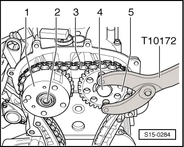
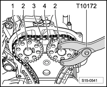
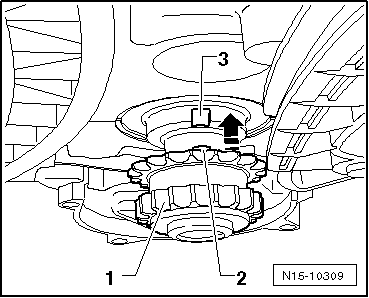
| Screw on the chain sprocket -3- by hand with a new fixing screw. |
| –
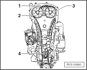
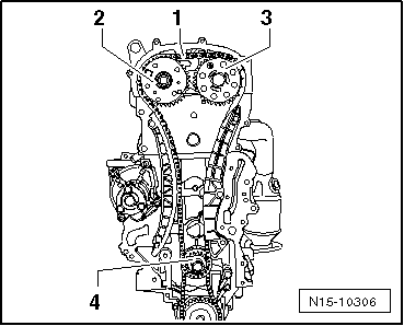
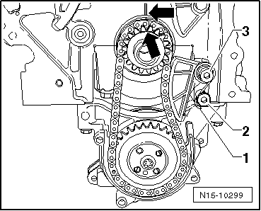
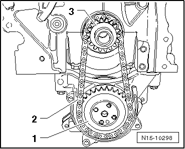
| Place the timing chain -1- onto the chain sprocket of the crankshaft -4-, the chain sprocket of the outlet camshaft -3- and screw on the camshaft adjuster -2- with a new fixing screw. |

Note | t
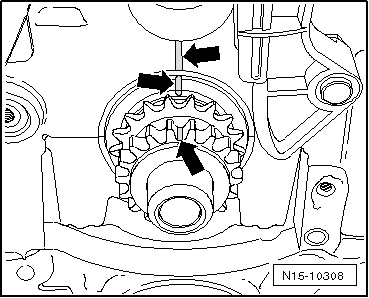
| Observe the marking of the running direction on the timing chain -1-. |
| t
| Make sure that the guide sleeve is installed between the inlet camshaft and camshaft adjuster. |
| t
| On engine with identification characters BTS, the fixing screw of the camshaft adjuster -2- has a left-hand thread. |
| For engine with identification characters CFNA, CLSA |
|
|
|

 Caution