Skoda Workshop Service and Repair Manuals
HOME
FEATURES
MENU
INDEX
ABOUT US
Inspecting the camshaft position sensor G163 >
< Removing and installing ignition system
Octavia Mk1
Drive unit
1.4 ltr./44 kW Engine, Simos 3PB Fuel Injection and Ignition System
Ignition system, glow plug system / Ignition system
Check ignition coils with power output stage
Check ignition coils with power output stage
Check ignition coils with power output stage
Special tools and workshop equipment required
t
Hand multimeter (e.g. -V.A.G 1526 A-)
t
Voltage tester (e. g. -V.A.G 1527 B-)
t
Adapter cable set (e.g. -V.A.G 1594 A-)
t
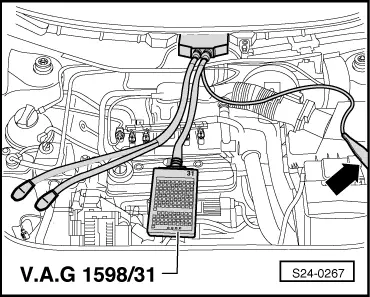
Test box -V.A.G 1598/31-
t
Current flow diagram
Test conditions
l
Battery voltage at least 11 volts
l
Engine speed sender o.k., test
→ Chapter
l
The fuse 29 must be o.k.
Note
Ignition coils and power amplifier are a common component (ignition terminal) and cannot be replaced individually.
Checking voltage supply
–
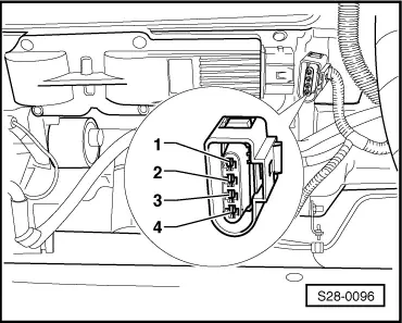
Pull out the 4-pin plug from the power output stage of the ignition coils.
–
Measure the power supply between the contacts 2 + 4 of the removed plug using the multimeter and the adapter cables from -V.A.G 1594 A-.
–
Switch on ignition.
Specified value: approx. battery voltage
–
Switch off ignition.
If no voltage is present:
–
Check the cable between 4-pin plug contact 4 and earth for interruption according to the current flow diagram.
Cable resistance: max. 1.5 Ω
–
Check cable between 4-pin plug contact 2 and relay plate for interruption according to the current flow diagram.
Cable resistance: max. 1.5 Ω
Test control
WARNING
During the following test do not touch the connecting parts of the ignition coils or the test cables.
–
Unplug connectors from the fuel injection valves.
–
Pull out the 4-pin plug from the power output stage of the ignition coils.
Voltage tester with adapter cables from -V.A.G 1594 A - to:
Contacts 1 + 4 (ignition outlet 1)
Contacts 3 + 4 (ignition outlet 2)
of the remove plug.
–
Actuate the starter and check the ignition signal on the engine control unit.
The LED must flash.
–
Switch off ignition.
If the LED flashes and there is a voltage existing between contact 2 and 4:
–
Replace ignition terminal
→ Chapter
.
If the LED does not flash:
–
Connect the test box -V.A.G 1598/31- to the wiring loom of the engine control unit
→ Chapter
.
–
Check wiring between the test box and the 4-pin plug for interruption according to the Current Flow Diagram:
Contact 1 and bush 112
Contact 3 and bush 113
Cable resistance: max. 1.5 Ω
–
Also check the wires for short-circuits.
Specified value: ∞ Ω
If no fault was detected in the wiring and if there is a voltage detected between contact 2 and 4:
–
Replacing engine control unit
→ Chapter
.
Drive unit
1.4 ltr./44 kW Engine, Simos 3PB Fuel Injection and Ignition System
Ignition system, glow plug system / Ignition system
Check ignition coils with power output stage
Inspecting the camshaft position sensor G163 >
< Removing and installing ignition system
 Note
Note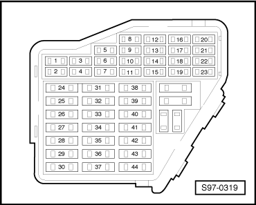
 WARNING
 Note
Note