Octavia Mk1
|
|
|
|
|
|
|
|
|
|
|
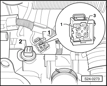
| 4-pin plug on wiring loom, contact | Test box -V.A.G 1598/31-, bush | |
| 1 | 104 | |
| 3 | 83 |
|

|
|
|
|
|
|
|
|
|
|
|
| 4-pin plug on wiring loom, contact | Test box -V.A.G 1598/31-, bush | |
| 1 | 104 | |
| 3 | 83 |
|