Octavia Mk1
|
|
|
|
|
|
|
|
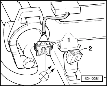
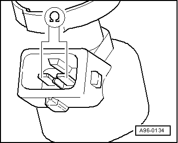
| Contact to connector plug | Measure against | |
| 1 | Engine mass | |
|
|
|

|
|
|
|
|
|
|
|
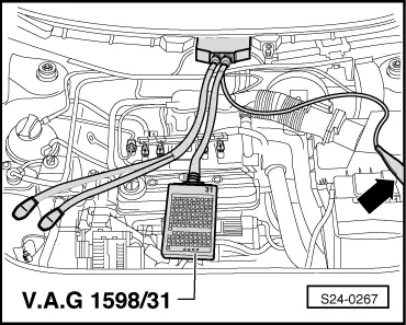
| Contact to connector plug | Measure against | |
| 1 | Engine mass | |
|
|
|