skoda Workshop Repair Guides

Skoda Workshop Service and Repair Manuals

Testing the compression > < Removing and installing camshaft housing
Removing and installing cylinder head
Special tools and workshop equipment required
t  Torque wrench
t  
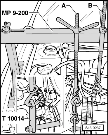
Supporting device -MP 9-200 -
t  Counterholder -T10014-
t  Counterholder -T30004-
t  Camshaft lock -T10016 -
t  Sealant -D 188 003 A1-
t  Catch pan, e.g. -V.A.G 1306-
t  Pliers for spring strap clips
Removing
Requirements
l  Engine temperature max. 20 °C
l  The pistons must not be in TDC.
–  Removing the camshaft housing → Chapter.
–  Open and close the cap of the expansion reservoir to reduce the pressure in the cooling system.
–  Drain coolant → Chapter.
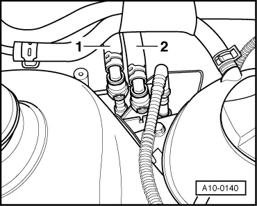
–  Release spring strap clamps and disconnect the coolant hoses of the coolant regulator housing.
  Note
After the hoses are separated, remaining coolant flows out; place the drip tray below for this purpose.
–  Unscrew the front exhaust pipe from the exhaust manifold and hook up → Chapter.
  Note
t  Self-tapping screws are used as standard for attaching the air filter to the plastic intake manifold and for attaching the air filter top part to the air filter bottom part. If these screws are released or tightened with an electrical screwdriver, the thread in the intake manifold or air filter bottom part may be damaged. For this reason, only use an electrical screwdriver, if:
t  the screwdriver speed is 200 rpm
t  the tightening torque is max. 3 Nm.
–  Remove the guide tube from the oil dipstick.
   
–  Detach the fuel feed line -1- and the fuel return-flow line -2-.
–  Disconnect the following components:
t  Hose from the crankcase ventilation
t  Hose from the activated charcoal filter system
t  Vacuum hose from the exhaust gas recirculation valve
t  the 2-pin plug from the knock sensor (rear cylinder block) and the 4-pin plug from the intake manifold pressure sender
t  the 2-pin plug from the engine speed sender and pull the plug out of the holder
t  Plug connection of the throttle valve control unit.
t  Connector of coolant temperature sender and exhaust gas recirculation valve.
  A10-0140
–  Unplug connector -arrows- of the injectors.
–  Remove the fuel rail with injection valves and lay aside → 1.4 ltr./55 kW Engine - Fuel Injection and Ignition System; Rep. Gr.24.
–  Remove exhaust manifold from cylinder head → Chapter.
Both lifting eyes are located on the cylinder head: an additional holder must be fitted on the cylinder block to support the engine
–  Remove the guide pulley for toothed belt drive.
  N24-0736
–  Raise engine with spindle -B-.
–  Screw in bracket -T10014- in the location of the removed guide pulley.
–  Raise engine with spindle -A- until spindle -B- is relieved.
–  Release spindle -B- and take out of the cylinder head holder.
–  Remove the retaining clip on the coolant regulator housing, which secures the coolant pipe to the coolant pump.
  S13-0237
–  Remove the cylinder head bolts in the recommended sequence.
–  Carefully remove the cylinder head.
Installing
  Note
t  Remove cylinder head gasket from its wrapping immediately before fitting.
t  Treat the new gasket with the utmost care. Any damage will result in leaks.
–  Make sure that when cleaning the cylinder head and cylinder block no foreign bodies can get into the cylinder or into the oil and coolant galleries.
–  When conducting repairs sealant residues should be removed from the contact surface of the cylinder head/cylinder block using a chemical cleaner.
–  Position piston of the cylinder 1 on TDC.
–  Lock the camshaft sprockets with -T10016-.
–  Position the new cylinder heads. The legend (spare part no.) must be legible.
–  Insert the cylinder head. Pay attention to the centering pins in the cylinder block.
–  Insert new screws and tighten by hand.
  N15-0026
–  Tighten the cylinder head bolts in the specified order.
–  Tighten all bolts to 30 Nm + torque a further 1/4 turn (90°).
–  Then tighten all bolts once again + torque a further 1/4 turn (90°).
–  Insert the hydraulic supporting elements in the cylinder head and position the relevant roller rocker arm on the valve stem ends.
–  Installing camshaft housing → Chapter.
The further assembly is carried out in reverse order to disassembly.
–  Filling system with coolant → Chapter.
  V15-0738

Testing the compression > < Removing and installing camshaft housing