| The following appears in the display: |
| The read-out for the partial load must be on “0010”. (When opening the throttle valve, the idling switch opens at the same time). |
| –
| If the specified values are not reached, switch off the ignition and connect the test box -V.A.G 1598/22- to the wiring loom of the engine control unit → Chapter. |
| –
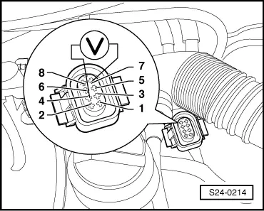
| Measure the resistance between the sockets 67 and 69 using a handheld multimeter. |
| Specified value: continuity, max. 1.5 °Ω. (Throttle valve shut) |
| –
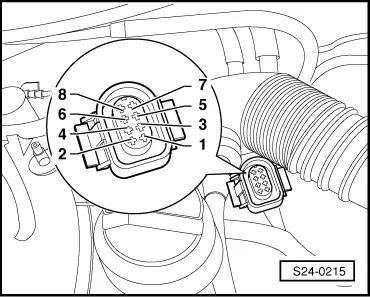
| Slightly open throttle valve. |
| Specified value: ∞ Ω (no continuity) |
| –
| If the specified value is not reached, check the wiring and the contacts for continuity, damage or contamination according to the current flow diagram, if necessary clean or replace damaged parts → Current flow diagrams and Fitting locations. |
| –
| Then adapt the engine control unit to the throttle valve control unit → Chapter. |
| –
| If the specified value is not reached again, check throttle valve for dirt and/or resistance and clean if necessary. |
| –
| Repeat adaptation of the throttle valve control unit → Chapter. |
| –
| If the adaptation cannot be started or successfully completed, replace the throttle valve control unit. |
| –
| Perform adaptation of the throttle valve control unit → Chapter. |
| Inspect sender for throttle valve positioner and throttle valve potentiometer |
| –
| Unplug the 8-pin connector from the throttle valve control unit. |
|
|
Reading measured value block 2 -> | 1000/rpm 120 mg/s 0 km/s 0010 |
|

 Note
Note