skoda Workshop Repair Guides

Skoda Workshop Service and Repair Manuals

Test air mass meter G70 > < Inspecting the injection rate, tightness and jet formation of the injectors
Test fuel pump relay and control
Special tools and workshop equipment required
t  Handheld multimeter, e.g. -V.A.G 1526 A -
t  Voltage tester, e.g. - V.A.G 1527-
t  Measuring tool set -V.A.G 1594 A -
t  Test box -1598/22-
  Note
   
The fuel pump relay is located in the electrical centre in the left footwell, relay position 4.
A - check fuel pump relay -J17-
–  Remove storage in front left of footwell.
  S24-0289
–  Disconnect fuse for fuel pump (fuse 28) at the fuse holder and connect the voltage tester between earth and one of the two contacts of the fuse for the fuel pump → Current flow diagrams and Fitting locations.
–  Switch on the starter motor for a short time.
The fuel pump relay must be activated (feel and hear), the voltage tester must light up.
–  If the fuel pump relay does not connect, test control → Anchor.
–  If the voltage tester does not light up even though the fuel pump relay is activated, repeat the test on another contact.
  S97-0319
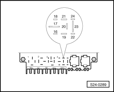
–  If the voltage tester does not light up again, check the cable connection between contact 23 at the relay position 4 and check the fuse for fuel pump for continuity and if necessary eliminate open circuit → Current flow diagrams and Fitting locations.
–  If the power supply, the actuation and the wiring of the fuel pump relay are O.K, replace the fuel pump relay.
B - Check voltage supply and actuation of the fuel pump relay
  Note
The actuation of the fuel pump relay can also be checked by means of the final control diagnosis → Chapter.
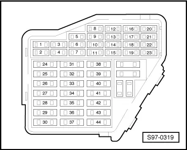
–  Remove the fuel pump relay - J17- from the relay carrier, relay position 4.
Checking voltage supply
–  Switch on ignition.
–  Connect the multimeter successively to the contacts 19 (positive, terminal 15 from the ignition lock) of the relay base and earth as well as 17 (permanent positive, terminal 30 of the battery) of the relay base and earth.
Specified value: approx. battery voltage each
–  If the specified values are not reached, eliminate line interruption → Current flow diagrams and Fitting locations.
Test control
  S24-0289
–  Connect the voltage tester to contact 16 of the relay base (earth control of the engine control unit) and to positive.
–  Switch on the starter motor for a short time.
–  The voltage tester must light up continuously when operating the starter.
  Note
Voltage testers with low power consumption do not go out fully but keep on glowing until the starter is operated.
–  If the actuation of the fuel pump relay as well as the cable connection and the voltage supply are O.K, however the fuel pump relay is not activated, the fuel pump relay must be replaced.
If the voltage tester does not light up, test wiring as follows:
–  Connect the test box -V.A.G 1598/22- to the wiring loom of the engine control unit → Chapter.
–  Connect hand multimeter between contact 16 of relay base and socket 4 of the test box and test wiring for continuity.
–  If necessary eliminate line interruption → Current flow diagrams and Fitting locations.
–  If there is no open circuit and the voltage tester does not light up, replace the engine control unit → Chapter.
–  Re-insert the fuse for the fuel pump.
  S24-0289

Test air mass meter G70 > < Inspecting the injection rate, tightness and jet formation of the injectors