
Octavia Mk1
| Removing and installing crankshaft |
 Note
Note| t | Before removing the crankshaft, ensure a suitable place is available for placing it down so that the sensor rotor → Item does not rest on anything or get damaged. |
| t | To carry out removal and installation operations, attach the engine with the engine holder -MP 1-202- and the sleeves -T30010- to the assembly stand -MP 9-101- → Chapter 10-1. |
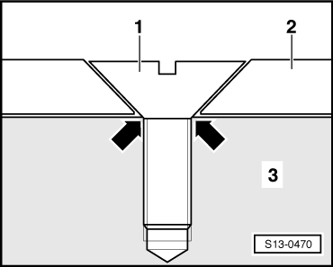
| t | Pay attention to colour coding when inserting bearing shells → Fig. |

| 1 - | Oil pump |
| q | removing and installing → Chapter 17-1 |
| 2 - | 15 Nm |
| 3 - | Sprocket |
| q | for oil pump drive |
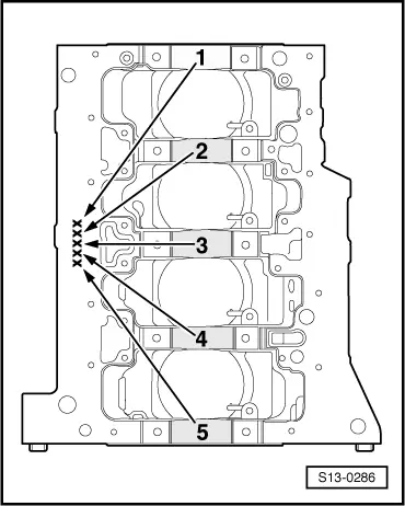
| 4 - | Bearing shells 1, 2, 3, 4 and 5 |
| q | Identification for ordering replacement parts → Fig. |
| q | for bearing cap without lubricating groove |
| q | for cylinder block with lubricating groove |
| q | do not mix up used bearing shells (mark) |
| 5 - | 40 Nm + torque a further 90° (1/4 turn) |
| q | replace |
| q | tighten thread |
| 6 - | Bearing caps |
| q | Bearing cap 1: on the belt pulley side |
| q | retaining lugs of the bearing shells of the cylinder block/bearing cap must be on top of one another |
| 7 - | Rotor |
| q | for engine speed sender -G28- |
| q | assembly only possible in one position -holes offset- |
| q | replace sensor rotor each time the bolts are slackened |
| q | removing and installing → Fig. |
| 8 - | 10 Nm + torque a further 90° (1/4 turn) |
| q | replace |
| 9 - | Crankshaft |
| q | Axial play when new: 0.07…0.23 mm |
| Wear limit: 0.30 mm |
| q | Crankshaft bearing journal: Ø 48.00 mm |
| q | Conrod bearing journal: Ø 42.00 mm |
| 10 - | Thrust washer |
| q | for bearing 3 |
| q | Fitting position: Oil grooves point to the crank webs |
Note
|
|
| S | = | black |
| R | = | red |
| G | = | yellow |
| B | = | blue |
| W | = | white |
|