skoda Workshop Repair Guides

Skoda Workshop Service and Repair Manuals

Installing cylinder head > < Removing and installing cylinder head
Removing cylinder head
l  Engine installed
Precondition
l  Engine cold
Special tools and workshop equipment required
t  Support for conrod -MP 1-225-
t  
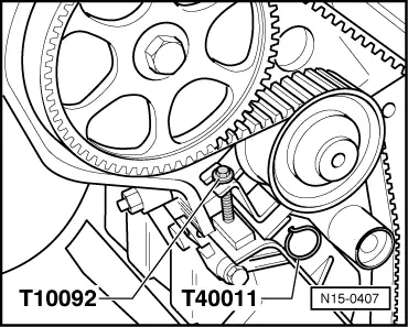
Locking pin e. g. -T40011-
t  Threaded pin M5x55
t  Key e.g. -3452-
  Note
All cable straps which are detached or cut open when removing, should be fitted on again in the same place when installing.
–  On models fitted with a coded radio set, pay attention to the coding; determine if necessary.
–  Disconnect the earth strap from the battery with the ignition off.
–  Remove engine cover.
–  Drain coolant → Chapter.
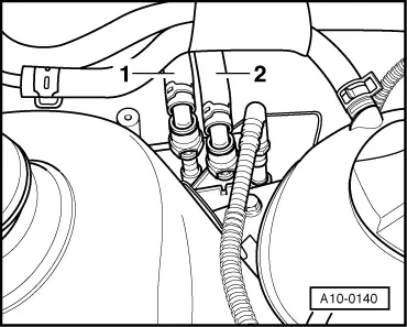
–  Disconnect intake air hose from the throttle valve.
–  Disconnect the plug connector on the throttle valve.
For vehicles with mechanical accelerator control
   
–  Detach the vacuum hose -2- at the throttle valve.
–  Unhook the throttle control cable at the throttle valve control unit and intake manifold support -arrows- (do not remove plug-in catch) and place the throttle control cable to the side.
For vehicles with electronic power control
–  Detach the vacuum hose at the throttle valve and detach the activated charcoal filter system.
Continued for all vehicles
–  Disconnect plug:
–  for intake air temperature sender -G42-
–  for hall sender -G40-
–  for knock sensor I -G61-
–  for engine speed sensor -G28-
–  for knock sensor ll -G66-
–  from the oil pressure switch -F1-
–  Spark plug connector
–  for coolant temperature sender -G62-
–  from charge pressure control solenoid valve - N75-. Fitting locations → 1.8 litre/110 kW engine, fuel injection and ignition system Motronic; Rep. Gr.24.
–  Unplug plug connectors at the injection valves and place the wiring harness to the side.
–  Detach vacuum lines.
For vehicles with secondary air injection system
–  Remove secondary air hose from intake manifold bracket.
Continued for all vehicles
–  Remove reservoir for vacuum with bracket for cylinder head screw and place to the side.
  WARNING
The fuel system is under pressure! Before opening the system lay cleaning cloths around the connection point. Reduce pressure by carefully releasing the connection point.
  A10-0212
–  Detach the fuel feed line -1- and the fuel return-flow line -2-.
–  Remove the hose of the crankcase ventilation at “T” piece.
–  Remove the V-ribbed belt and clamping fixture → Chapter.
–  Remove the generator → Electrical System; Rep. Gr.27.
–  Unscrew intake manifold support.
–  Pull out oil dipstick.
–  Unscrew left coolant flange from cylinder head and and lay it to the side.
–  Unplug the connectors at the ignition coils.
–  Secure all the lines at the cylinder head and expose.
–  Remove air guide pipe for charge air system from exhaust turbocharger to charge air cooler → Chapter.
–  Remove exhaust turbocharger from exhaust manifold → Chapter.
–  Remove noise insulation and right engine cover.
  A10-0140
–  Position crankshaft in direction of rotation of engine to TDC marking of cylinder 1 -arrows-.
  A15-0024
–  Screw the - T10092- clamp bolt into the tensioning device for the toothed belt.
–  Tension pressure piston of tensioning device just sufficiently to enable the pressure piston to be secured with a locking pin (e.g. -T40011-).
–  Take toothed belt off camshaft sprocket.
–  Unscrew ignition coils.
–  Remove cylinder head cover → Chapter.
  N15-0407
–  Slacken the cylinder head bolts with a wrench -3452- in the sequence shown in the figure.
–  Remove cylinder head.
  A15-0134

Installing cylinder head > < Removing and installing cylinder head