| Removing and installing crankshaft |

Note | t
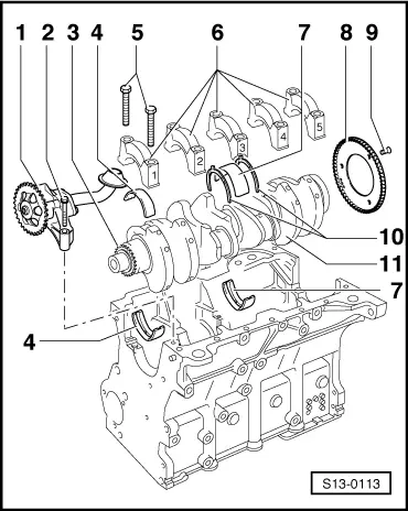
| Before removing the crankshaft, ensure a suitable place is available for placing it down so that the sensor rotor does ( → Chapter, Pos 8) not get damaged. |
| t
| The engine should be attached to the engine repair stand -MP 1-202- with engine holder -MP 9-201- for carrying out installation work. |
| 4 - | Bearing shells 1, 2, 4 and 5 |
| –
| for bearing cap without lubricating groove |
| –
| for cylinder block with lubricating groove |
| –
| used bearing shells must not be mixed up (mark) |
| –
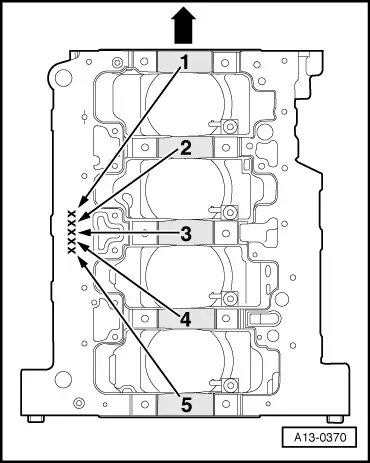
| In case of replacement, pay attention to different versions. On engines with bearing shells of different colours, bearing shells of the same colour must be installed → Fig. |
| 5 - | 65 Nm + torque a further 90° (1/4 turn) |
| –
| Bearing cap 1: on the belt pulley side |
| –
| Bearing cap 3: with recesses for thrust washers |
| –
| retaining lugs of the bearing shells of the cylinder block/bearing cap must be on top of one another |
| –
| for engine speed sender -G28 - |
| –
| assembly only possible in one position -holes offset- |
| 9 - | 10 Nm + torque a further 90° (1/4 turn) |
| –
| for bearing cap and cylinder block, bearing 3 |
| –
| pay attention to the marking |
| –
| Crankshaft bearing journal: Ø54,00 mm |
| –
| Conrod bearing journal: Ø47,80 mm |
|
|
|