
Octavia Mk1
 Note
Note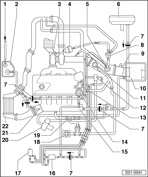
| 1 - | Vent line |
| q | from fuel tank |
| 2 - | Activated charcoal filter |
| q | with activated charcoal filter system solenoid valve 1 -N80 - |
| 3 - | Exhaust turbocharger |
| 4 - | Charge pressure control valve pressure unit |
| 5 - | Stroke switch-off valve |
| 6 - | Brake servo unit |
| 7 - | Non-return valve |
| q | fitting location (bright/dark side): see figure, arrow points in direction of passage |
| 8 - | Solenoid valve for charge pressure control -N75- |
| q | test → 1.8 litre/110 kW engine, fuel injection and ignition system Motronic; Rep. Gr.24. |
| 9 - | Air mass meter -N70- |
| 10 - | Air filter |
| 11 - | Crankcase ventilation pressure control valve |
| 12 - | Combination valve for secondary air inlet |
| 13 - | Vacuum unit |
| q | screwed onto the cylinder head cover |
| 14 - | Fuel pressure regulator |
| 15 - | Intake manifold |
| q | Intake air temperature sender -G42- |
| 16 - | Turbocharger divert air valve - N249- |
| q | test → 1.8 litre/110 kW engine, fuel injection and ignition system Motronic; Rep. Gr.01. |
| 17 - | Secondary air injection valve -N112 - |
| q | test → 1.8 litre/110 kW engine, fuel injection and ignition system Motronic; Rep. Gr.24. |
| 18 - | Crankcase ventilation |
| 19 - | Suction spray pump |
| 20 - | Secondary air pump |
| q | removing and installing → Chapter |
| 21 - | Throttle valve control unit -J338 - |
| 22 - | Charge air cooler |
| q | Charge pressure sender -G31- |