Note | t
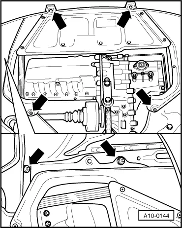
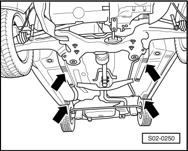
| The engine is removed downwards together with the gearbox. |
| t
| All cable straps that have been loosened or cut open when the engine was removed must be fitted again in the same location when the engine is installed again. |
| t
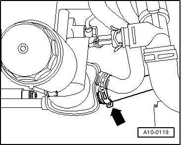
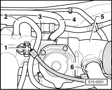
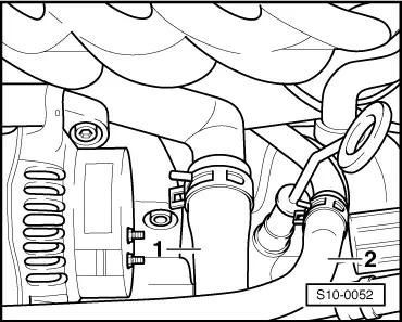
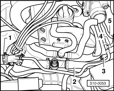
| The hose connections are secured with screw-type clips, spring-type clips or clamp-type clips. |
| t
| Always replace clamp-type clips with screw-type clips or spring-type clips. |
| t
| Fuel lines on the engine must always be secured with spring-type clips. The use of clamp-type or screw-type clips is not allowed. |
| t
| Use pliers for spring strap clips to remove and fit the spring strap clips. |
| t
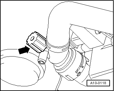
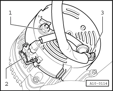
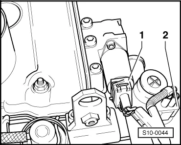
| Pay attention to correct assignment of the corresponding connectors, if necessary mark. |
| –
| On models fitted with a coded radio set, pay attention to the coding; determine if necessary. |
| –
| Switch off the ignition and disconnect the battery earth strap. |
| –
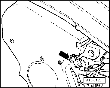
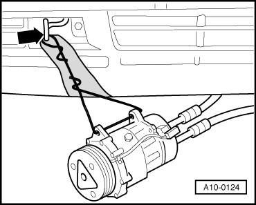
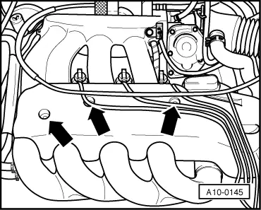
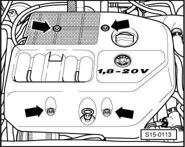
| Unhook throttle cable on the throttle valve control unit and at the support at induction pipe (do not remove connector catch). |
| –
| Unclip throttle cable and ignition leads from the ignition cable guide. |
|
|
|

 WARNING