skoda Workshop Repair Guides

Skoda Workshop Service and Repair Manuals

Grinding in valve seats > < Testing the compression
Repairing Valve Gear
  Note
Cylinder heads with cracks between the valve seats may be continue to be used without any reduction in the life time provided the cracks are slight and max. 0.5 mm wide.
1 - Bearing caps
–  Fitting position → Fig.
–  order of installation → Chapter
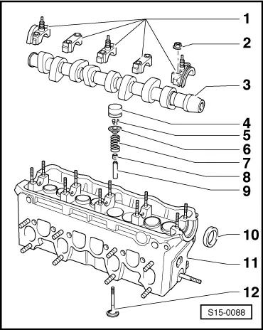
–  Seal the contact surface of bearing caps 1 and 5 with sealant -AMV 174 004 01-.
2 - 20 Nm
3 - Camshaft
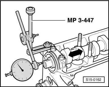
–  Inspecting axial play → Fig.
–  removing and installing → Chapter
–  Slack: max. 0.01 mm
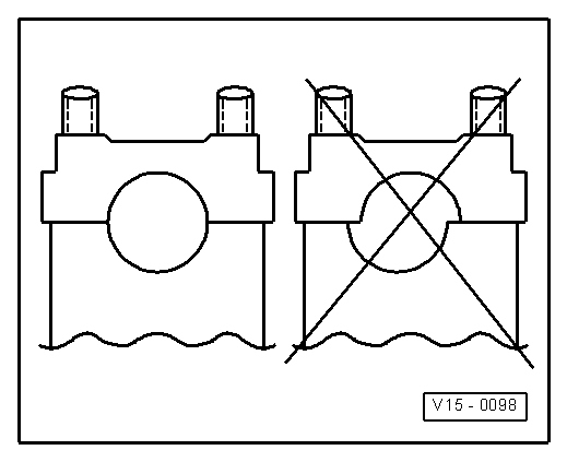
–  Camshaft identification → Fig.
4 - Bucket tappets
–  do not interchange
–  with hydraulic valve clearance compensation
–  check → Chapter
–  lay aside with contact surface facing down
–  before installing check axial play of the camshaft → Fig.
–  oil contact surface
5 - Collets
6 - Valve spring retainer
7 - Valve spring
–  removing and installing: cylinder head removed: with -MP 1-218 -, -MP 1-211- and -MP 1-213 -, cylinder head installed: → Chapter
8 - Valve stem seal
–  replace → Chapter
9 - Valve guide
–  check → Chapter
–  replace → Chapter
10 - Sealing ring
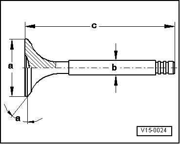
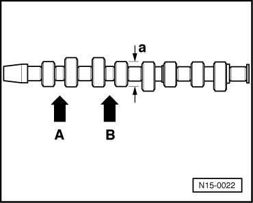
–  pay attention to different version → Fig.
–  to remove and install, the bearing cap and the toothed belt gear must be removed
–  before fitting cover slot on the camshaft cone with commercially available adhesive tape (e.g. Scotch tape).
–  Removing and installing timing belt → Chapter
11 - Cylinder head
–  pay attention to note → Anchor
–  Grinding in valve seats → Chapter
12 - Valve
–  Valve dimensions → Fig.
  S15-0088
inspect camshaft, axial play
Special tools and workshop equipment required
t  Universal dial gauge holder -MP 3-447-
t  Dial gauge
Wear limit: max. 0.15 mm
Perform measurement with the bucket tappets removed and the first and last bearing cap fitted.
  S15-0162
Fitting position of the camshaft bearing cap
  Note
Pay attention to centre displacement. Before installing the camshaft fit bearing cap and determine the fitting position.
  V15-0098
Valve dimensions
  Note
Valves must not be reworked. Only grinding in is permissible.
  V15-0024
DimensionInlet valveExhaust valve
Ø amm35,9531,45
Ø bmm6,9636,943
cmm96,8596,85
α∠°4545

   
Gasket ring versions
I - Elastomer gasket ring
   Sealing lip -1-; with garter spring
II - PTFE gasket ring
   multiple sealing lips -2-; without garter spring
  Note
t  Do no moisten the PTFE gasket ring with oil before inserting. The shaft must also be free from oil and grease.
t  Never install an elastomer gasket ring (old version), if a PTFE gasket ring (new version) was fitted.
t  A PTFE gasket ring can be installed, if an elastomer gasket ring was installed.
  S13-0190
Camshaft identification
t  Base circle of the cam: a = Ø 35 mm
t  Identification with digits and characters stamped in between the inlet and outlet cams
  N15-0022
Cylinder 1 -arrow A-38A
Cylinder 2 -arrow B-DE


Grinding in valve seats > < Testing the compression