| –
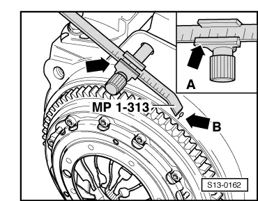
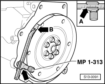
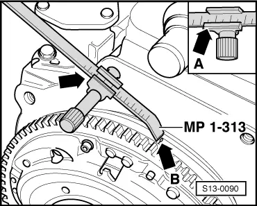
| Screw in adjusting device for TDC point -MP 1-313-, as shown in the fig. |
| –
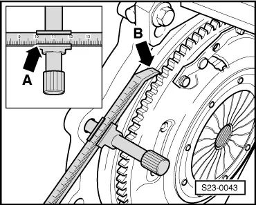
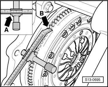
| Set adjusting device to 96 mm -arrow- (the left notch on the vernier -arrow A- is the reference point). |
| –
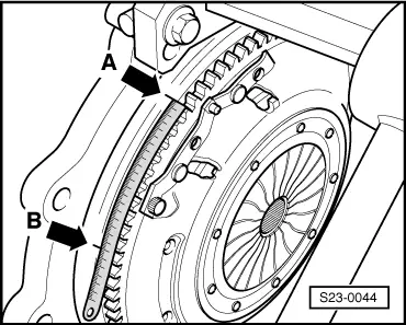
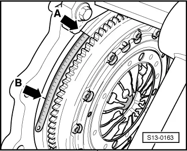
| Rotate crankshaft until the TDC marking -arrow B- on the flywheel corresponds with the edge of the adjusting device. |
|
|
|