
Octavia Mk1
|
|
|
 Note
Note
|
|
|
|
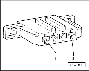
| 4-pin plug on wiring loom, contact | Specification |
| 3 + earth | approx. battery voltage |
|
|
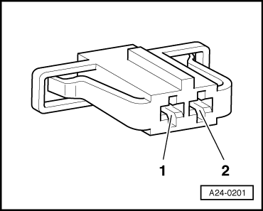
| 2-pin plug on wiring loom, contact | Specification |
| 1 + earth | approx. battery voltage |
Note
|
|
|
| 4-pin plug on wiring loom, contact | Test box - V.A.G 1598/31-, bush |
| 2 | 66 |
|
|
| 2-pin plug on wiring loom, contact | Test box - V.A.G 1598/31-, bush |
| 2 | 66 |
|