
Octavia Mk1
|
|
|
|
|
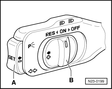
| Switch position of the CC switch | 10-pin plug on CCS switch, contact | Specification |
| Switch B on “ON” | 4 + 5 6 + 7 | max. 1.5 Ω |
| Switch B on “RES” | 4 + 5 2 + 7 6 + 7 | max. 1.5 Ω |
| Switch A pressed | 3 + 7 | max. 1.5 Ω |
| Switch B pressed to “OFF” | 6 + 7 4 + 5 | max. 1.5 Ω ∞ Ω |
| Switch B switched to “OFF” | 6 + 7 2 + 7 4 + 5 | ∞ Ω |
|
|
|
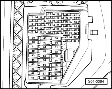
| 10-pin plug on CCS switch, contact | Test box -V.A.G 1598/31-, bush |
| 2 | 45 |
| 3 | 44 |
| 4 | 14 |
| 5 | 46 |
| 7 | 14 |
|