
Octavia Mk1
| Individual components of system - Installation overview |
| For engines with identification characters AEG, APK, AQY, AZH |
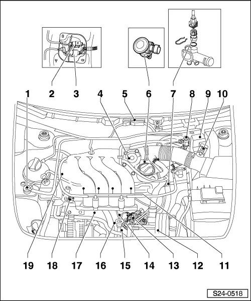
| 1 - | Activated charcoal filter solenoid valve -N80-*/** |
| q | Activated charcoal filter → 2.0 ltr./85 kW Engine, Mechanics → Rep. Gr.20 |
| 2 - | Plug connection for lambda probe upstream of catalytic converter |
| q | for engines with engine identification characters AEG, APK, AQY - 4-pin |
| q | for engines with identification characters AZH - 6-pin |
| q | driver side on right |
| 3 - | Plug connection for lambda probe downstream of catalytic converter |
| q | for engines with identification characters AQY, AZH |
| q | 4-pin |
| q | driver side on right |
| 4 - | Throttle valve control unit -J338-* |
| 5 - | Engine control unit -J220-* |
| q | below the water box cover |
| 6 - | Combination valve |
| q | for engines with identification characters AQY, AZH |
| 7 - | Coolant temperature sender -G62 -* |
| q | resistances → Fig. |
| 8 - | Secondary air injection valve -N112 -*/** |
| q | only engines with identification characters AQY, AZH ? 07.2000 |
| q | valve internal resistance 25...45 Ω |
| q | Secondary air pump → 2.0 ltr./85 kW Engine, Mechanics → Rep. Gr.26 |
| 9 - | Relay carrier |
| q | only engines with identification characters AQY, AZH |
| q | the secondary air pump relay is also located here -J299- |
| q | the Motronic current supply relay is also located here -J217- |
| 10 - | Air mass meter -G70-* with intake air temperature sender -G42-* |
| 11 - | Injectors -N30-...-N33-*/** |
| q | → Item |
| 12 - | Secondary air pump -V101- |
| q | only engines with identification characters AQY, AZH |
| q | Secondary air pump → 2.0 ltr./85 kW Engine, Mechanics → Rep. Gr.26 |
| 13 - | Ignition transformer * |
| q | with power output stage -N122- |
| q | with ignition coils -N-, -N128- |
| q | check → Chapter |
| 14 - | Knock sensor 2 -G66-* |
| 15 - | Engine speed sender -G28-* |
| q | inductive pickup |
| q | Fitting location: under the oil filter in the cylinder block |
| q | → Item |
| 16 - | 3-pin connector |
| q | grey for engine speed sender -G28- |
| 17 - | Knock sensor 1 -G61-* |
| 18 - | Fuel pressure regulator |
| 19 - | Camshaft position sensor -G40 -* |
| q | check → Chapter |
| For engines with identification characters AZJ |
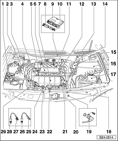
| 1 - | Activated charcoal filter solenoid valve -N80-*/** |
| q | Activated charcoal filter → 2.0 ltr./85 kW Engine, Mechanics → Rep. Gr.20 |
| 2 - | Return-flow line |
| q | secure with spring strap clip |
| 3 - | Feed line |
| q | secure with spring strap clip |
| 4 - | Camshaft position sensor -G40-* |
| 5 - | Valve for variable intake manifold changeover -N156- |
| 6 - | Top part of intake manifold |
| q | disassembling and assembling → Chapter |
| 7 - | Bottom part of intake manifold |
| q | disassembling and assembling → Chapter |
| 8 - | 81-pin plug |
| q | insert and remove plug when the ignition is switched off |
| q | unlock for removing |
| 9 - | Engine control unit -J220-* |
| q | below the water box cover |
| 10 - | 40-pin plug |
| q | insert and remove plug when the ignition is switched off |
| q | unlock for removing |
| 11 - | Throttle valve control unit -J338 -* |
| 12 - | Combination valve |
| q | Secondary air pump → 2.0 ltr./85 kW Engine, Mechanics → Rep. Gr.26 |
| 13 - | Relay carrier |
| q | the secondary air pump relay -J299- and the Motronic current supply relay -J271- is also located here |
| 14 - | Coolant temperature sender -G62 -* |
| q | resistances → Fig. |
| q | with coolant temperature gauge sensor -G2- |
| q | before removing, reduce pressure in cooling system if necessary |
| 15 - | Air mass meter -G70-* with intake air temperature sender -G42-* |
| 16 - | Air filter |
| q | disassembling and assembling → Chapter |
| 17 - | Main fuse box |
| 18 - | ignition coil with power output stage (-N70-, -N127-, -N291-, -N292-) |
| 19 - | Engine speed sender -G28-* |
| q | inductive pickup |
| q | Fitting location: under the oil filter in the cylinder block |
| q | → Item |
| 20 - | Secondary air pump -V101- |
| q | Secondary air pump → 2.0 ltr./85 kW Engine, Mechanics → Rep. Gr.26 |
| 21 - | Injectors -N30-...-N33-*/** |
| q | → Item |
| q | with air ring |
| 22 - | Knock sensor 2 -G66-* |
| 23 - | Knock sensor 1 -G61-* |
| 24 - | Valve 2 for variable intake manifold changeover -N261- |
| 25 - | Plug connection for lambda probe downstream of catalytic converter |
| q | 4-pin |
| q | driver side on right |
| 26 - | Lambda probe after catalyst -G130 -*, 50 Nm |
| q | Fitting location: in exhaust pipe downstream of catalytic converter |
| q | coat only thread with hot bolt paste - G 052 112 A3-; the hot bolt paste must not get into the slots of the probe body |
| q | Testing lambda probe and lambda control downstream of catalytic converter → Chapter |
| 27 - | Plug connection for lambda probe upstream of catalytic converter |
| q | 6-pin |
| q | driver side on right |
| 28 - | Lambda probe upstream of catalytic converter -G39-*, 50 Nm |
| q | Fitting location: in the exhaust manifold |
| q | coat only thread with hot bolt paste - G 052 112 A3-; the hot bolt paste must not get into the slots of the probe body |
| q | Testing lambda probe and lambda control upstream of catalytic converter → Chapter |
| q | Check lambda probe ageing before catalyst → Chapter |
| 29 - | Fuel pressure regulator |
| q | Test fuel pressure regulator and holding pressure → Chapter |