skoda Workshop Repair Guides

Skoda Workshop Service and Repair Manuals

Test CAN databus for short-circuit > < Checking the data BUS drive
Check the terminating resistances of the control units
Check the terminating resistance of all the control units according to the databus cables.
Procedure
–  Connect test box -V.A.G 1598/33 - to wiring loom of the ABS/ESP control unit, or test box - V.A.G 1598/21- to wiring loom of the ABS control unit.
–  Remove all the control units, except the ones to be checked, from the databus cables.
  Note
To check the terminating resistance of the 121-pin engine control unit, the other CUs must not be disconnected from the databus cables, the resistance must be checked after connecting the test box -V.A.G 1598/31- to the engine control unit.
–  Measure the resistance between the test box sockets 10 and 11 on the test box -V.A.G 1598/21-, if necessary 19 and 20 on the test box 1598/33.
Specified resistance values:
   
Control unit? MY 99MY 00 ?
Engine control unit110 to 130 Ω60 to 72 Ω
CU ABS/ESP110 to 130 Ω2.35 to 2.85 kΩ
Control unit with display in dash panel insert2.35 to 2.85 kΩ2.35 to 2.85 kΩ
CU for automatic gearbox2.35 to 2.85 kΩ2.35 to 2.85 kΩ
CU for four-wheel drive2.35 to 2.85 kΩ2.35 to 2.85 kΩ
CU for airbag2.35 to 2.85 kΩ2.35 to 2.85 kΩ

If the specified values are not reached:
–  Replace the relevant control unit.
  Note
If random damage of the databus cables is suspected, check the terminating resistance directly on each CU.
Check terminating resistance of the engine control unit
–  Disconnect connector from control unit and unplug.
For engines with 121-pin engine control unit
–  Connect test box -V.A.G 1598/31 - to the 121-pin engine control unit. The wiring loom to the engine control unit is not connected.
–  Check terminating resistance in the engine control unit.
For petrol engines with 121-pin engine control unit
–  Measure resistance between the test box sockets 58 and 60.
For diesel engines with 121-pin engine control unit
–  Measure resistance between the test box sockets 6 and 7.
For engines with 80-pin engine control unit
Vehicles with ABS
–  Connect test box -V.A.G 1598/21 - to wiring loom for ABS CU.
–  Measure resistance between the test box sockets 10 and 11.
Vehicles with ESP
–  Connect test box -V.A.G 1598/33 - to wiring loom for ABS/ESP CU.
–  Measure resistance between the test box sockets 19 and 20.
Continued for all engines
Specified resistance values:
   
? MY 98110...130 Ω
MY 99 ?60...72 Ω

If the specified value is not reached:
–  Replacing engine control unit:
→ Injection and ignition system for diesel engines, Rep. Gr. 24.
→ Injection and ignition system for diesel engines, Rep. Gr. 23.
If the specified value is reached:
–  Unplug the test box from the engine control unit, if necessary the wiring loom of the ABS control unit.
–  Test data BUS wiring for short-circuit to each other, for short-circuit to positive battery or earth and/or for open circuit → Chapter.
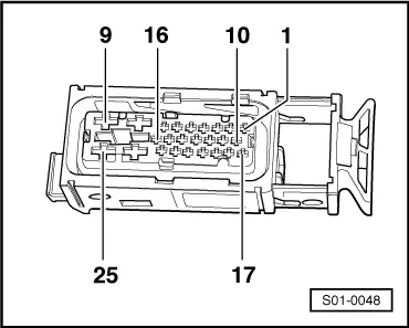
Check terminating resistance of CU for ABS - J104-
   
–  Measure the resistance between the terminals 10 and 11 at the connector for ABS CU -J104-.
For vehicles with ESP
  S01-0048
–  Measure the resistance between the terminals 10 and 20 at the connector for ESP CU -J104-.
For both systems
Nominal resistance value:
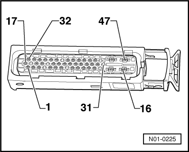
  N01-0225
? MY 98110...130 Ω
MY 99 ?2.35 to 2.85 kΩ

Check terminating resistance of CU for dash panel insert -J218-
–  Measure the resistance between the terminals 19 and 20 at the green 32-pin connector for dash panel insert → Chapter.
Specified resistance value: 2.35 to 2.85 kΩ
Check terminating resistance of CU for four-wheel drive -J492-
–  Measure the resistance between the terminals 7 and 8 at the 8-pin connector for CU -J492-.
Specified resistance value: 2.35 to 2.85 kΩ
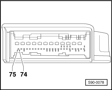
Check terminating resistance of CU for airbag -J234-
   
–  Measure the resistance between the terminals 74 and 75 at the connector for CU -J234-.
Specified resistance value: 2.35 to 2.85 kΩ
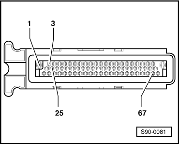
Check terminating resistance of CU for automatic gearbox -J217-
  S90-0078
–  Measure the resistance between the terminals 3 and 25 at the connector for CU -J217-.
Specified resistance value: 2.35 to 2.85 kW
Continued for all control units
If the specified value is not reached:
–  Replace the relevant control unit.
  S90-0081

Test CAN databus for short-circuit > < Checking the data BUS drive