
Octavia Mk1
 Note
Note
|
 WARNING
| 1 - | Defroster vent - side window |
| t | remove: carefully lever out |
| 2 - | Outer dash panel vent |
| t | remove: carefully lever out |
| 3 - | Defroster vent - windscreen |
| t | remove: carefully lever out, remove plug of sunlight penetration photosensor -G107- |
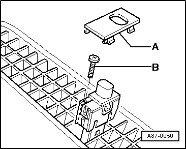
| 4 - | Sunlight penetration photosensor -G107- |
| t | Function: depending on the intensity of the sunlight controls the temperature flap and the fresh air blower |
| t | Emergency operation in the event of failure: Climatronic control unit -J255- adopts fixed value |
| t | check: by the self-diagnosis |
| t | removing and installing → Fig. |
| 5 - | Centre dash panel vent |
| t | Unit with warning light switch |
| t | remove: carefully lever out, remove plug from warning light switch |
| 6 - | Dash panel temperature sensor -G56- with Temperature sensor blower -V42- |
| t | the components, i.e the Climatronic control unit -J255-, the Control and display unit for air conditioner, Climatronic -E87- and the dash panel temperature sensor -G56- with the temperature sensor blower -V42- cannot be disassembled |
| t | check: by the self-diagnosis |
| t | Function: the temperature sensor controls the temperature flap and the fresh air blower according to the temperature |
| t | Emergency operation in the event -G56- fails: System keeps running at an assumed value of + 24°C |
| t | after replacing: function 07 “code control unit” → Chapter and subsequently perform function 04 “basic setting” → Chapter |
| 7 - | Control and display unit -E87- |
| t | the components, i.e the Climatronic control unit -J255-, the Control and display unit for air conditioner, Climatronic -E87- and the dash panel temperature sensor -G56- with the temperature sensor blower -V42- cannot be disassembled |
| t | check: by the self-diagnosis |
| t | Control and operation → Chapter |
| t | removing and installing → Chapter |
| t | after replacing: function 07 “code control unit” → Chapter and subsequently perform function 04 “basic setting” → Chapter |
| 8 - | Intermediate piece for centre dash panel vent |
| t | only for climatronic |
| t | is fitted in the air guide duct for the dash panel vent |
| t | removing and installing with the dash panel |
| 9 - | Middle vent temperature sender -G191- |
| t | Vehicles with mapped cooling |
| t | remove and install and test → Chapter |
| 10 - | Air guide duct for the dash panel vent |
| t | screwed on the distributor box, locked on the top |
| 11 - | Fresh air intake duct temperature sensor -G89- |
| t | Function: the temperature sensor controls the temperature flap and the fresh air blower according to the temperature |
| t | Emergency operation in the event of failure: The Ambient temperature sensor -G17- performs the task |
| t | check: by the self-diagnosis |
| t | replace: |
| Remove the glove compartment → Body Work; Rep. Gr.70 |
| – | Rotate the temperature sensor 90° and pull out |
| – | when fitting moisten the rubber seal with oil |
| 12 - | Air flow flap control motor -V71 - |
| t | operated simultaneously with the fresh air and re-circulating air flap |
| t | check: by the self-diagnosis |
| t | replace → Chapter |
| t | adjust: Perform function 04 “basic setting” → Chapter |
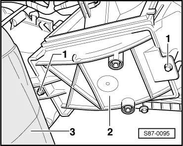
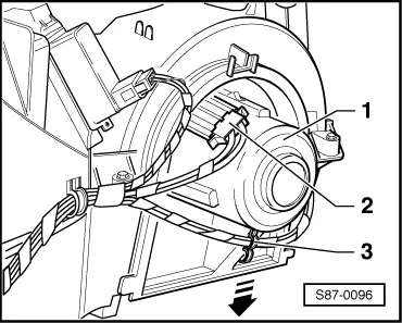
| 13 - | Fresh air blower -V2- |
| t | check: by the self-diagnosis |
| t | removing → Fig. |
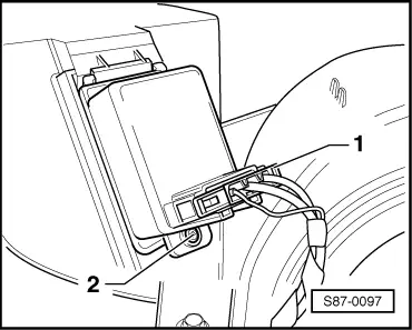
| 14 - | Fresh air blower control unit -J126- |
| t | Function: smoothly controls the output of the fresh air blower in accordance with the voltage values |
| t | check: by the self-diagnosis |
| t | replace → Fig. |
| 15 - | Air conditioning unit* |
| t | with heat exchanger |
| t | with evaporator |
| t | removing and installing → Chapter |
| 16 - | Control motor for temperature flap -V68- |
| t | check: by the self-diagnosis |
| t | replace → Chapter |
| t | adjust: Perform function 04 “basic setting” → Chapter |
| 17 - | Control motor for centre flap -V70- |
| t | check: by the self-diagnosis |
| t | replace → Chapter |
| t | adjust: Perform function 04 “basic setting” → Chapter |
| 18 - | Centre part of dash panel |
| t | removing and installing → Body Work; Rep. Gr.70 |
| 19 - | Climatronic control unit -J255- |
| t | the components, i.e the Climatronic control unit -J255-, the Control and display unit for air conditioner, Climatronic -E87- and the dash panel temperature sensor -G56- with the temperature sensor blower -V42- cannot be disassembled |
| t | check: by the self-diagnosis |
| t | removing and installing → Chapter |
| t | replace: function 07 “code control unit” → Chapter and subsequently perform function 04 “basic setting” → Chapter |
| 20 - | Footwell vent |
| t | only passenger side |
| 21 - | Rear duct |
| 22 - | Connecting piece to rear duct |
| 23 - | Footwell vent |
| t | removing and installing → Chapter |
| 24 - | Footwell vent temperature sender -G192- |
| t | Function: controls the defrost/footwell air distribution and the output of the fresh air blower in accordance with the vent temperature |
| t | Emergency operation in the event of failure: System keeps running at an assumed value of +80°C coolant temperature |
| t | check: by the self-diagnosis |
| t | removing and installing → Fig. |
| 25 - | Footwell flap and defroster flap control motor -V85- |
| t | check: by the self-diagnosis |
| t | replace → Chapter |
| t | adjust: Perform function 04 “basic setting” → Chapter |
| 26 - | Heat exchanger* |
| t | after removing the coolant must be completely replaced |
| t | removing and installing → Chapter |
| 27 - | Gasket heat exchanger/bulkhead* |
| t | check fitting position → Chapter |
| 28 - | Air guide duct to the defroster vents |
| t | removing and installing → Chapter |
| 29 - | Evaporator vent temperature sender -G263-* |
| t | Vehicles as of 03.01 |
| t | remove and install, test → Chapter |
|
|
|
|
|
|
|
|