skoda Workshop Repair Guides

Skoda Workshop Service and Repair Manuals

Repairing gearbox housing and gearshift shaft > < Disassembling gearbox
Assembling gearbox
Assembling gearbox
–  Insert the differential gear.
–  Insert output shaft.
–  Tighten screws for the bearing support/output shaft.
   
–  Fitting position of thrust washer for needle bearing 1st gear sliding gear:
Shoulder -A- on the inside diameter points towards the bearing support -B-.
–  Position thrust washer, needle bearing, sliding gear and 1st gear synchronizer ring.
  V34-2571
–  Fitting position of the 1st and 2nd gear sliding sleeve/synchronizer body:
The groove marking on the front side -A- and the outer serration of the sliding sleeve -B- point to the 1st gear shift gear -C-.
  V34-2572
–  Heat 1st and 2nd gear sliding sleeve/synchronizer body to approx. 100 °C, press on and drive in play-free up to the stop.
   Rotate the synchronizer ring in such a way that the slots are flush with the arresters.
–  Install reverse gear, thus drive in axle if necessary.
  S34-0096
–  Driving on inner ring for needle bearing 2nd gear sliding gear up to the stop.
–  Position needle bearing, synchronizer ring, 2nd gear sliding gear and 3rd gear pinion.
  S34-0097
Fitting position of 3rd gear pinion
Collar -arrow- to 2nd gear sliding gear -A-.
–  Drive in 3rd gear pinion up to stop with drive bushing -MP3-402 (VW 244 B)-.
  V34-2573
Set axial play at 3rd gear pinion as follows:
–  Determine the thickest circlip - that can be fitted - and insert.
The following circlips are available:
  V34-1427
Spare part No.Thickness (mm)Identification
020 311 381 F2,5Brown
020 311 381 G2,6black
020 311 381 H2,7blank
020 311 381 J2,8copperize
020 311 381 K2,9brazen
020 311 381 L3,0blue

  Note
t  If the drive shaft was not disassembled:
t  Press off grooved ball bearing for drive shaft → Chapter Pos. 10.
t  Remove tensioning plate of ball bearing → Chapter Pos. 11.
–  Insert drive shaft completely without grooved ball bearing.
   
–  Mount supporting bridge -MP3-425 (30-211 A)- for drive shaft.
A - Counternut M12
–  Lift the pressing tool -T30087/2 (3367/2)- over the screw onto the drive shaft up to the stop and lock with nut -A-.
  S34-1251
Fitting position of 4th gear pinion
Collar -arrow- points to 5th gear sliding gear -A-.
–  Position 4th gear sliding gear onto output shaft, drive in with drive bushing -MP3-402 (VW 244 B)- and secure with circlip.
  S34-0098
–  Press on grooved ball bearing/drive shaft.
Fitting position:
Broad collar -arrow- at inner ring points to the pressing tools.
  Note
To ensure that the dowel sleeves for centering the gearbox housing cover on the gearbox housing do not get damaged, they must be removed from the gearbox housing beforehand.
  S34-0099
–  Tighten tensioning plate of ball bearing -arrow A-.
  Note
The tensioning plate of the ball bearing fits only in one position -arrow B-.
  S35-0093
–  Before installing the shift fork set, secure the lower spring -arrow- to the shift rod or insert it into the clutch housing.
  V34-2465
–  Install shift fork set and align shift gates.
-A- 1st/2nd gear shift fork. -Arrow- points to the recess for the switching bridge -C-.
-B- 3rd/4th gear shift fork
-C- Switching bridge with shift tube for 5th gear.
-D- Shift fork reverse gear.
–  Push in gearshift rod.
  V34-2575
–  Align reverse shaft support. Distances -x- are the same.
–  Apply sealant -AMV 188 200 03- uniformly on the sealing surface of the clutch housing.
  V35-0070
–  Drive on the gearbox housing, while doing so pay attention that the drive shaft is perfectly supported by the supporting bridge -MP3-425 (30-211 A)- → Anchor.
–  Tighten reverse shaft support.
–  Tighten the screws for securing the gearbox housing to 25 Nm.
–  Tighten oval-head countersunk screws to 15 Nm on the tensioning plate for grooved ball bearing.
–  Drive in 5th gear pinion
  S34-0519
Fitting position:
The groove -arrow- points upwards.
–  Position thrust washer and circlip.
–  Position 5th gear synchronizer body completely with sliding sleeve, sliding gear and 5th gear shift fork and new lock washer.
–  Screw shift tube with pipe wrench -MP3-433 (3059)- towards the right in the shift fork.
  S34-0101
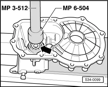
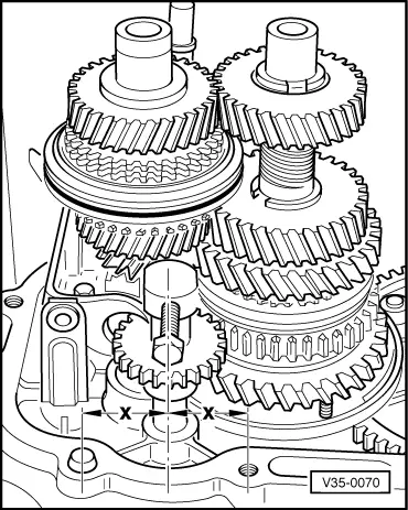
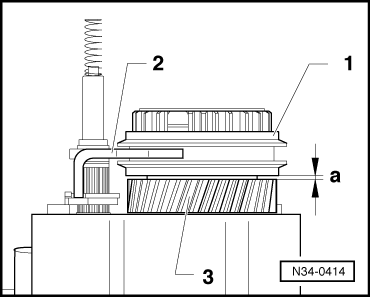
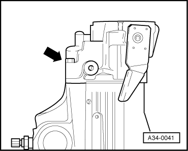
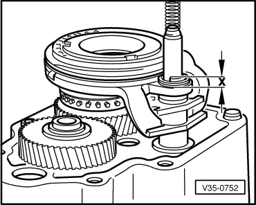
–  Screw out shift tube so far until a projection -x- = 5.0 mm is reached.
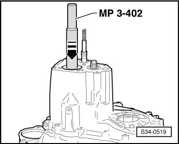
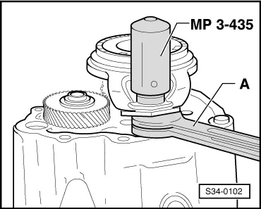
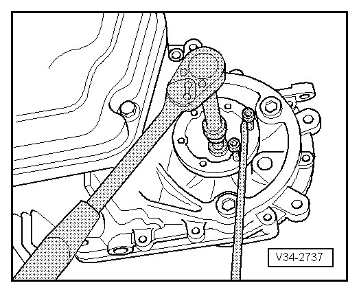
  Note
Do not pull shift rod out of the shift tube (possibly through tilting of the pipe wrench), otherwise the shift forks in the gearbox come apart and the gearbox must be dismantled again. If necessary, hold down the shift rod with a screwdriver when removing the pipe wrench through the lateral slot.
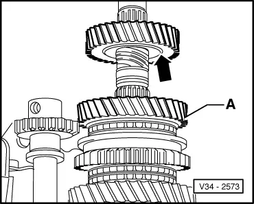
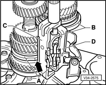
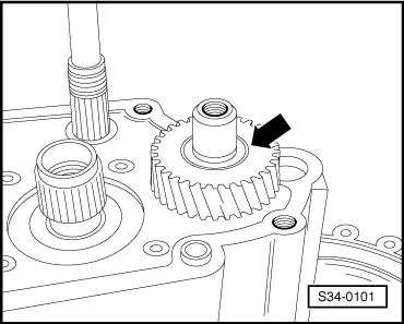
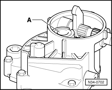
–  Position new screw for synchronizer body with disc spring.
l  The new screw must be micro encapsulated. If not, coat the screw with locking agent -D 000 600 A2-.
l  
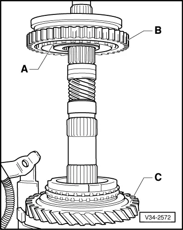
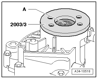
Fitting position of the disc spring: the outside diameter (concave side) points to the 5th gear.
  V35-0752
–  Engage 5th gear -arrow 1-.
–  Engage reverse gear -arrow 2- (front shift fork to the bottom).
–  Tighten screw for synchronizer body using a 12 mm polygon head wrench.
–  Put shift forks in neutral position before installing the gearshift shaft.
  V34-2552
–  Carefully insert gearshift shaft -1- so that the gasket ring for gearshift shaft is not damaged. If necessary, pull the shrink hose over the serration of the gearshift shaft.
–  Insert pressure spring -2- for gearshift shaft and tighten screw cap -3- with new O-ring -4-.
Up to gearbox manufacturing date 02 08 8
–  Insert locking screw for gearshift shaft/reversing light switch -F4--5- with sealant -AMV 188 200 03-.
  A34-0045
As of gearbox manufacturing date 03 08 8
–  Screw in the reversing light switch -F4--1-.
–  Screw in locking screw -2- for gearshift shaft with sealant -AMV 188 200 03-.
Continued for all gearboxes
Set 5th gear shift fork as follows:
  Note
The setting must be performed with particular care so that “jumping out of gear” can be excluded.
  N34-1173
–  Check projection of the shift tube - measurement “x” = 5.0 mm, if necessary adjust with pipe wrench -MP3-433 (3059)-.
–  Screw the lever for the gearshift shaft onto the gearshift shaft and engage 5th gear (pull out gearshift shaft completely and turn to the left).
  V35-0752
–  Align sliding sleeve -1- with shift fork -2- clearance free to 5th gear sliding gear -3-.
l  Control measurement: between sliding sleeve and sliding gear there must be a dimension of “a” = 1.3 mm. Correct the dimension if necessary by turning the shift tube.
–  Remove 5th gear. The sliding sleeve must now be in Neutral. The synchronizer ring must travel freely.
  N34-0414
–  Insert an approx. 12 mm thick base between the shift fork and the housing, e. g. two open-end wrench -A- of 19 mm.
–  Drive in new lock washer with driver -MP3-435 (3097)-.
  Note
When supporting the shift fork do not damage the sealing surface of the gearbox housing.
–  Shift through all gears.
–  Apply sealant -AMV 188 200 03- uniformly on the sealing surface of the gearbox housing.
  S34-0102
–  Install cover -arrow- for gearbox housing (6 screws).
  Note
One of the 6 screws is located inside the cover.
  A34-0041
–  Then insert the release bearing -A- in the gearbox housing cover.
  N34-0702
–  Install a new screw cap -A-, to do so use a drawing ring -T30036/3 (2003/3)-.
  Note
The sealing surface at the cap for the gearbox housing must be free of grease.
  A34-10518
–  Fill half the space between the sealing lip and dust lip, the gasket rings for flange shaft, with sealing grease -G 052 128 A1--arrow-.
  N32-0001
–  Install both flange shafts with pressure springs, stop discs and conical rings.
–  Remove supporting bridge -30 - 211 A- for drive shaft.
  V34-2737
–  Insert the clutch push rod -A- in the drive shaft -direction of arrow-.
  N34-0701

Repairing gearbox housing and gearshift shaft > < Disassembling gearbox