
Octavia Mk1
|
|
|
 Note
Note
|
|
|
|
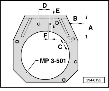
| -A- | = 118.5 mm | |
| -B- | = 23.5 mm | |
| Ø -C- | = 11.0 mm | |
| -D- | = 40 mm | |
| -E- | = 55 mm | |
| -F- | = M10 | |
|
Note |
|
|
|
|
|
|
Note
|
|
|
|
|
|
|
|
|
|
|
|
|
|
|
|
|
|
Note
|
|
|
|
|
|
|
|
|
|
|
|
|
|
|
|
Note
|
|
|
|
|
|
|
|
Note
|
|