
Octavia Mk1
|
|
 Note
Note
|
|
|
|
|
|
|
|
|
|
|
|
|
|
|
|
|
|
|
|
Note
Note
|
|
|
|
Note
|
|
|
|
Note
|
|
|
|
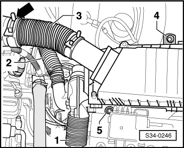
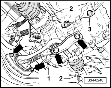
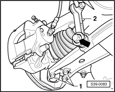
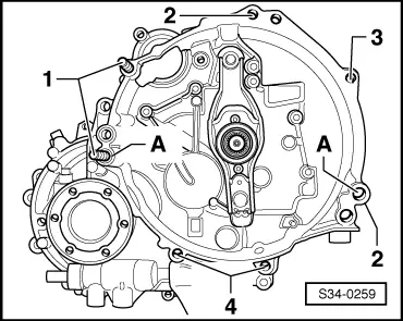
| Pos. | Nut/screw | Pieces | Nm |
| 1 | Nut M10 | 2 | 45 |
| 2 | Nut M10 | 2 | 45 |
| 3 → Note | Screw M10 | 1 | 45 |
| 4 | Screw M10 | 2 | 45 |
|
|
|
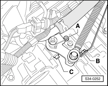
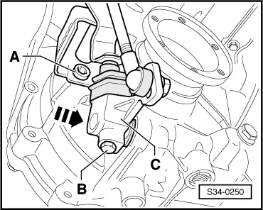
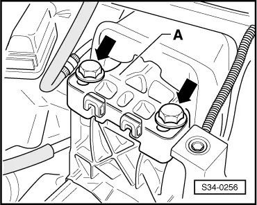
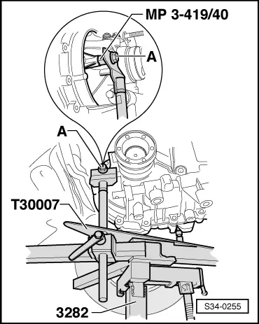
| Screw -A- for console and guide bush (speedometer) to gearbox | 20 Nm | |
| Screw -B- and -C- | 20 Nm | |
|
|
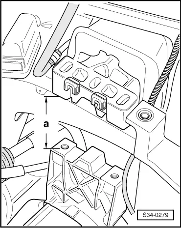
| Screw -A- | 20 Nm | |
| Screw -B- for attaching the gearbox shift lever -C- to the gearshift shaft → Note | 20 Nm | |
|
| Components | Tightening torque | |
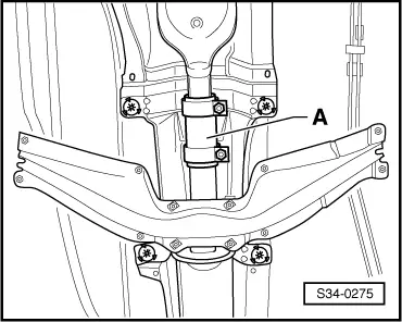
| Support angle - steering gear M8 | 25 Nm | |
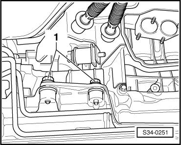
| Cover for gearbox housing - gearbox mount M12 → Note | 80 Nm | |
| Pendulum support - gearbox M10 → Note | 40 Nm + 90° | |
| Pendulum support - assembly carrier M8 → Note | 20 Nm + 90° | |
| Drive shaft - flange shaft (tighten crosswise in 2 stages) M8 → Note → Rep. Gr.40 | ||
| Steering joint - track control arm M8 → Note | 20 Nm + 90° | |
| Coupling rod - track control arm | 45 Nm | |
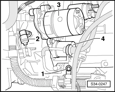
| Starter - gearbox M8 | 25 Nm | |
| Wheel bolts - wheel hub | 120 Nm | |
| Nut for attaching double clamp of exhaust system | 40 Nm | |
|